
by Hib Halverson
There are several reasons why a C3 do-it-yourselfer might want to replace a fuel tank. Most common, considering the youngest C3 is 36 years old, is a tank which has been damaged by rust and corrosion to the point that it is leaking. Another reason might be rust and corrosion debris have accumulated inside the tank such that fuel filters quickly become restricted. Other reasons could include collision damage or maybe or an incorrect fuel tank is discovered during a body-off restoration. The tank we replaced for this article was in a ’71 which had a significant fuel system rust and corrosion problem.
Zip Products sells three types of fuel tanks for the 1968-1982 cars. The first two types: reproduction replacement and restoration-quality reproduction replacement stamped with the logo of the original supplier, O.L. Anderson Company, are available for ’68-’82 applications. The third type is for cars being upgraded to electronic fuel injection and fits only ’68-’74 models. Additionally, when ordering a tank for any ’68-72, getting the model year correct before ordering is important because, prior to 1973, GM had a lot of different tank configurations. Be especially careful when ordering tanks for ’69s as not only are the tanks specific to certain engines, but there are early-’69 and late-’69 designs. If there is any question, email or call a Zip Products sales specialist before a purchase.
 We ordered a Zip Products standard reproduction tank to fit any ’70-’74 (PN GT-399) and a reproduction filler neck (PN GT-296). We also ordered one of Zip’s 1968-1974 Corvette gas tank installation kits (PN GT-383) which includes fuel tank mounting straps with anti-squeak pads, strap to frame mount bolts, gas tank lower support anti-squeak pads and fuel filler neck screws. Finally, we ordered a new Tank Pick-up assembly from Zip (PN GT-302) along with a Fuel Tank Sender Tool (PN TL-120) used to remove or replace the lock ring which retains the sender in the tank.

We ordered a 1971 Corvette Service Manual (PN B-353) from Zip just in case we needed factory service information on the ’71 fuel system. In general, the tools necessary to complete this job are those any intermediate automotive DIY should have. The exceptions are the above-mentioned tank sender tool, a very large pair of slip joint pliers and a large pry bar which will likely be needed towards the end of the project when the tank straps are installed.


01: The first step is to get the back of the car up in the air, either on a lift or on jack stands. We chose the latter as it’s more characteristic of how a DIY would do the work. Next, remove the spare tire and tire carrier. Remove the mufflers and other exhaust pieces as necessary. Our project car has two single-piece Flowmaster muffler/mid-pipe assemblies, so the entire exhaust system up to the center cross member had to come out.
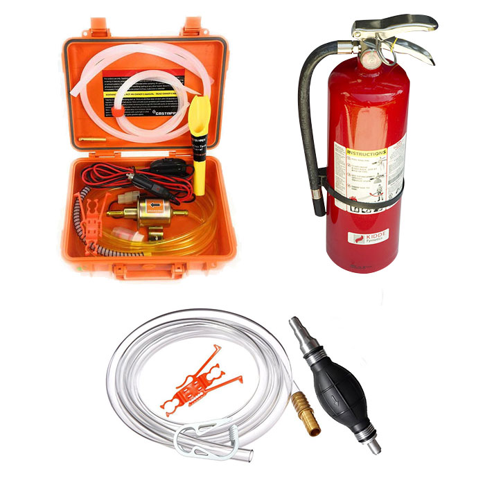
02: Next, drain the fuel tank into a gas can of appropriate volume. Do that in a well-ventilated area which has no open flame sources. Have a dry chemical fire extinguisher, rated 2-A20-B:C or better close by. There are several ways to drain the tank. The easiest is to disconnect the hose from the tank pick-up and let the fuel drain into a bucket. If you have a ’63-’81 modified with an electric fuel pump, disconnect the fuel line from the carburetor, aim it into a container then turn the key on, but don’t start the engine, and the pump will drain the tank. The last tank drain method is to obtain a siphon pump and hose and siphon the fuel out of the tank. GenTap’s “Siphon Pro” brand markets siphon-pumped gravity flow transfer hose kits which work quite well. The company’s “Gas Tapper” line has higher-cost, 12-volt electric transfer pump systems.

03: None of these methods will drain the tank dry, so once you’ve pumped or siphoned as much gas as you can out of the tank, either plug or pinch off the connection at the tank sender. Once you remove the tank, you can pour the small amount of gasoline left out of the vapor return hose nipple on the passenger side of the tank. Finally, to dispose of the fuel you have drained, if the gasoline is clean and relatively fresh and was drained into a clean container, put it in the fuel tank of another vehicle. In our case the fuel was five years old and contaminated with water, rust and corrosion so we disposed it in an environmentally responsible manner. How you do that may vary with local or state laws. We took our bad gas to a drain oil recycler.


04: Now that the fuel tank is drained, spray the tank strap tensioner bolts and the tank’s front support beam member nuts with a penetrating oil. Some of the best penetrants are made by Kano Labs in a spray cans branded “Aerokroil” or “Silikroil”. Let the penetrant work for several hours then remove both tank strap retention bolts. Remove the straps prying the front end of each strap out of the slots in the tank support beam. Pull the other end of each strap out of the hole in the rear crossmember then pull the straps down and out. Finally, remove one nut on each side of the fuel tank support beam. Loosen, but do not remove, the other two nuts.
With the newest C3 being nearly 40-years old, all the rubber fuel hoses associated with the tank should be replaced. Some tanks have as many as three hoses, two on the right (supply hose and a vapor return) and a single vapor return on the left. Once you get a hose clamp off, if you find a hose difficult to remove, just cut it then use a utility knife to split the remainder and twist it off the tank. Disconnect fuel gauge wires going to the tank pick-up.
Getting the tank out is fairly easy. The quick way to do it is have someone help you. While your assistant holds the tank in place, remove the remaining two nuts retaining the fuel tank support beam and remove it. With one person on each end of the tank, rotate the tank forward until it clears the rear crossmember then lower the tank down and out.

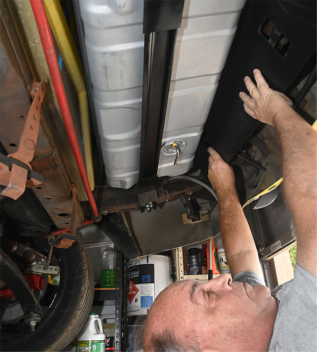
05: The tank can be easily removed by one person. Once you have the tank straps and two of the four fuel tank support beam nuts removed, devise a temporary method of holding the tank in place. I used a couple blocks of wood between the frame rails and the tank seams.

06: Then, I removed the last two support beam nuts and the beam itself. Finally, I pushed the tank up with one hand, removed the wood blocks, moved the tank forward a bit then tipped it down and out.
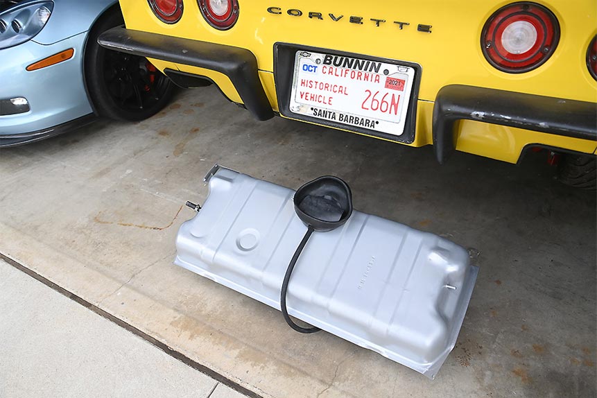
Now it was time to unbox the Zip Products repro fuel tank. Sitting on top of the tank in bags are parts Zip includes with every ’68-’74 repro tank: a tank pick-up retaining cam lock, pick-up O-ring seal, filler neck gasket and a set of filler neck screws. Once I had the Zip tank sitting next to the original, I was pleased to see that other than lacking the O.L. Anderson stamping, it looked just like the original, right down to the bracket for the evaporative emissions system vapor separator. What to do with an old fuel tank? Mine had no gas left in it, so I loaded it into the back of my pick-up and hauled it downtown to a scrap metal recycling center.


 07: Back at the shop, I lifted the new tank up onto the work bench then flipped it over to install the tank sender and pick-up assembly. I put the tank sender gasket in place, dropped the sender into the tank, put the cam on top of the sender and used Zip Products’ installation tool (PN TL-120) to lock the cam in place.

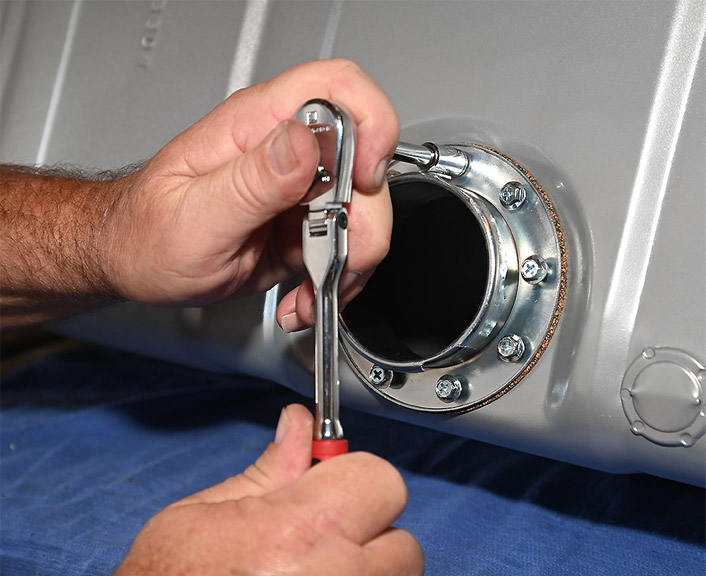
08: Before rolling the tank back over, I set a block of wood on the bench. Then, I set the tank on the block so the sender’s fuel outlet pipe was not supporting the weight of the tank. I laid the filler neck gasket in place, dropped the filler neck on top of it, inserted and started all the filler neck screws then tightened them in a star pattern so as to compress the neck gasket evenly.

09: With the filler neck in place, I added a Zip Products Filler Neck Boot (PN WS-623) to replace the original boot which was cracked and rotting. Apply some silicone spray to the inside edge of the boot then use your fingers push the boot over the top of the filler neck and down onto the top of the fuel tank. Orient the boot on the filler neck such that the hole for the overflow hose nipple points towards the rear of the tank.
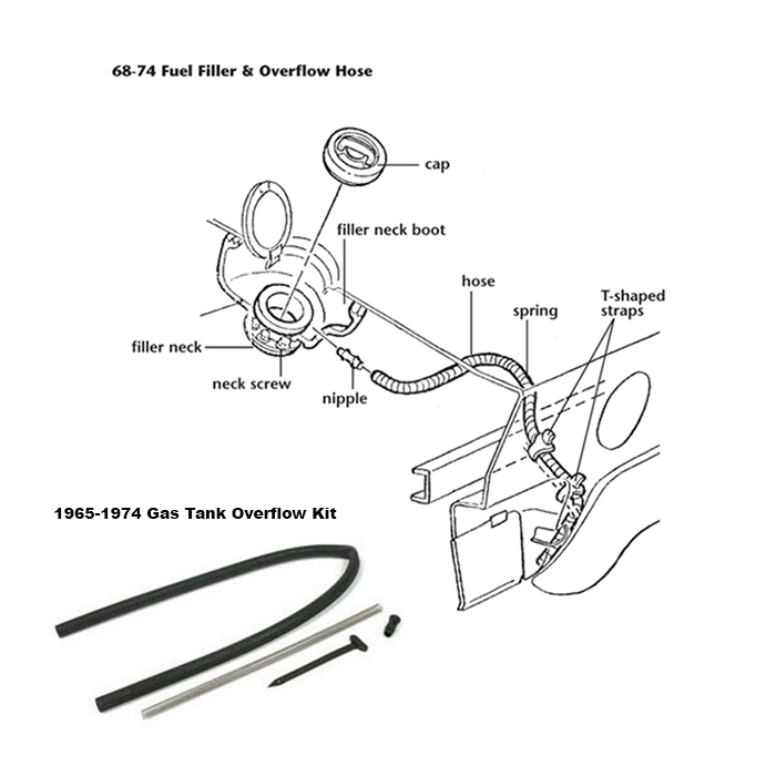 10: Not only was our car’s filler neck boot rotted, but the overflow hose was missing. GM put a short spring inside that hose, right where the hose curves around the tank’s rear edge and goes down alongside the tire carrier. The spring was to prevent the overflow drain hose from collapsing where it bends. While some folks just replace the hose, the right way is to buy Zip’s 65-74 Gas Tank Overflow Hose Kit (PN WS-4403) which includes both the nipple, the proper thin-wall hose, the spring and the correct tie straps.


11: It is virtually impossible to install that spring into the hose and correctly position it by hand. We started thinking of some kind of installation tool. As I looked through my rollaway for something to use to get that spring into the hose in the correct spot, I hit on using my 18-inch 1/4-in drive extension. It worked perfectly. I slipped the spring over the extension, then sprayed it with silicone. It was easy to push the spring all the way into the hose. Then I withdrew the extension, turned it around, used its large end to push the spring to the correct spot in the hose then pulled the extension back out. That took all of about a minute to do…after we spent 20-minutes fooling around trying to push it in the hose with our fingers. With the spring in the hose, I pushed the hose nipple into the filler neck boot, pushed the hose onto that then added a plastic clamp to retain the hose.
In some cases, the next step would be to install the evaporative emissions system vapor separator and hoses. If you need to replace those items, Zip Products stocks a reproduction separator (PN GT-380) and hose kit (PN CZ-1173). On my application, I was eliminating the evap system, so I did not install the separator and sealed off the hose connection on the driver side of the tank.

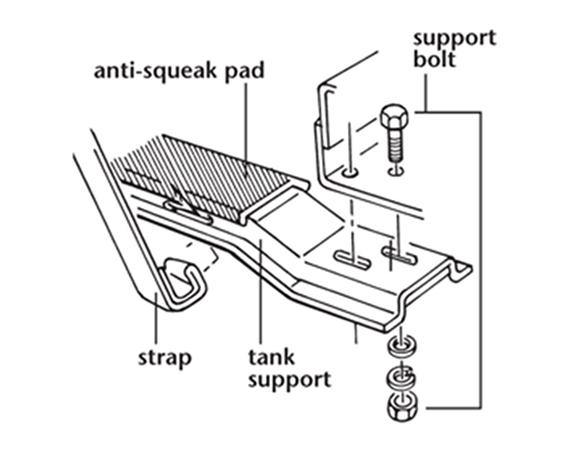

12: I got back underneath the car, laid one of the tank anti-squeak pads out of Zip’s Fuel Tank Installation Kit (PN GT-383) on the top of the rear crossmember. I lifted the tank up, rotated it slightly, then reinstalled my wood blocks between the top of the frame and the tank seam. Next, I cleaned and repainted the tank front support beam using Eastwood Rust Encapsulator and two coats of Eastwood Satin Chassis Black. After letting the paint dry overnight, I put the other anti-squeak pad on the top of the tank support beam. I installed the bolts from Zip Products lower tank support bolt kit (PN GT-320). I pulled out my temporary blocks, held the tank with one hand and put the tank support beam in place with the other. While holding the support beam in place with one hand, I started two of the support nuts with the other, one on each side. Once they were finger tight, I put the other two nuts on, finger tightened them, then tightened all four.
Now comes the most difficult part of a tank replacement: the gas tank straps. When these straps were put on at the St. Louis Assembly Plant fifty years ago, it was done before the body was dropped onto the chassis. Line workers applied the anti-squeak strips, the tank was lowered on the back of the frame, the straps were set in place then hooked in front and bolted at the rear. Finally, the bolts were tightened, likely with power-driven equipment. Doing this with the body on the car is far more difficult.


13: Lay the tank strap anti-squeak strips, which come in Zip’s tank installation kit, in the strap channels on the tank. Use four short strips of packing tape to hold the ends of the anti-squeak strips in place. Install Zip Products’ ’71-’74 Gas Tank Rear Shield (PN GT-319) by moving the tank rearward then sliding the shield up between the back of the tank and the rear crossmember. Next, install the reproduction tank straps from the installation kit. Start them at the rear of tank and on the outside of the tank shield. Push each strap up, through the two slots in the shield such that, where each strap runs though the slots, they are between the shield and the tank. Above and below the slots, the straps are outside of the shield. Move the tank rearwards so its two mounting indentations locate on the fuel tank support beam’s mounting pads. Hook the front of each strap into the slots on the tank support. I used a very large pair of slip-joint pliers to crush the ends of the straps locking them into the slots. Now, go back to the Tank Rear Shield and make sure its bottom edge butts up against the rear edge of tank anti-squeak pad between the rear corner of the tank and the rear crossmember. If necessary, adjust the position of the shield.


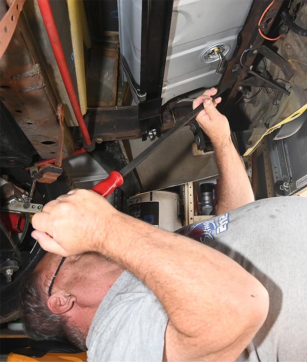
14: Stretch each tank strap so that the end with the threaded hole goes though the square passage in the rear crossmember. To align the strap’s threaded hole with the bolt that fastens it to the inside of the rear cross member may require a large screwdriver or pry bar. It may help to temporarily screw a couple of very short ⅜-in coarse bolts into the bolt holes such that your pry bar can pull on the bottom side of the bolt head stretching the strap enough that, once the pry bar is removed, you can remove the short bolts and start the retention bolt into the threaded hole in the strap. During this process we found that, despite the big pry bar, nothing we could do would stretch the strap far enough to where we could start the stock bolts. This is a common problem when replacing tank straps with the body on the frame. The solution is a pair of longer bolts. We used a pair of 2-in grade five bolts. We wiped some anti-seize lubricant on the threads, inserted them into the holes in each strap then tightened them securely.
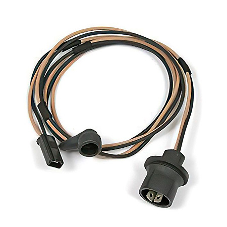 15: If you’ve gotten this far, you’re over the hump. The rest is easy. The fuel tank sender wiring harness may need some work. Typically, after almost 50 years, the rubber boot on the end of the tank sender’s signal wire will have hardened and the metal connector inside might be worn. There are two ways to fix this. The first is to replace the entire rear harness with reproduction parts from Zip Products (PN E-795 or E-1078) which is a good choice if there are other problems with rear lamps or this tank replacement is part of a body off restoration. The other way, if you don’t want to replace the entire rear harness, is to cut the old tank sender wires out of the rear light harness and splice new tank sender wires in place. To do that you need Zip Products’ 75-77 fuel tank sender harness (PN E-697).


16: Remove the left tailpipe shield which is screwed onto the rear fascia. Using a bright light, locate the two nuts which attach the rear lamp harness to the two-passenger side tail lamp housings and remove those nuts. Carefully pry the two plastic harness mounting tabs off the studs then pull that section of the rear lamp harness down to access the tank sender wires more easily. Cut the existing sender harness–a tan wire and a black wire–out of the rear lamp harness two or three inches below where it breaks out of the main lamp harness. Strip each wire’s insulation back about an eighth of an inch.


17: Take what you cut out off the existing rear lamp harness and lay it out, next to Zip’s ’75-’77 sender harness such that the tank sender ends of both are next to each other. Go to the other end of the old sender harness, then move two more inches up the new harness and cut the rest of the new harness off. Strip an ⅛-in of insulation off both wires. Using a crimp-on butt connector, join the brown wire of the new harness to the brown wire breaking out of the rear lamp harness. With another butt connector, do the same with the black wire.


18: Wrap the two butt connectors with black electrical or self-vulcanizing tape. Reattach the lamp harness to the two harness mounting studs and replace the nuts. Reinstall the tail pipe shield. Route the new sender wires through the harness retaining tab on the underside of the rear cross member then plug the sender signal wire to the signal post on the sender. Finally, connect the ground wire to the spade terminal on the sender.
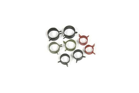
19: Install new hoses between the fuel tank and the various fuel lines running to and from the engine. If you insist on OE style spring clamps, Zip Products has an assortment of them (PN ZHC-515). If spring clips are not your thing, buy some screw clamps from your local auto parts source and install them to retain the hoses.
20: Reinstall the tire carrier, the spare tire and the exhaust system parts. Finally, put your fuel door assembly back on. Open it, remove the gas cap, add five gallons of fuel then start the engine and go for a drive.
1968-1982 Fuel Tank Replacement
Source: Zip Corvette Parts
8067 Fast Lane | Mechanicsville, VA 23111 | (800) 962-9632
Corvette Parts List Related to the Article:
- 1970-1974 Gas Tank
- 1968-1974 Gas Tank Installation Kit
- 1968-1974 Gas Tank Filler Neck Seal
- 1968-1974 Gas Tank Sending Unit
- 1963-1974 Gas Tank Sending Unit Tool
- 1968-1974 Gas Tank Filler Neck
- 1965-1974 Gas Tank Overflow Hose, Spring & Nipple Kit
- 1963-1982 Gas Tank Lower Support Mount Bolts
- 1971-1974 Gas Tank Plastic Rear Shield
- 1975-1977 Fuel Tank Sender Wiring Harness
- 1968-1982 Fuel System Frame Line Hose Clamps
- 1970-1974 Gas Tank Plastic Vapor Separator
- 1970-1974 Fuel Vapor Separator Hose Kit
- GearWrench Creeper
- GearWrench Work Light
- Gas Tapper 12V GT Max
- GenTap Siphon Pro
- Kano Labs SiliKroil
- Eastwood Rust Encapsulator
- Shop/Repair Manual
I wouldn’t use butt splices for the wires, they have a tendency to fail after a few years. I’d splice and solder the wires then use quality Scotch 33 black tape to wrap them up. That will last a lifetime.