
By Hib Halverson
Here at corvettemagazine.com, we hear reports of C6 and C7 Corvette owners who run hot weather track events having trouble with the engine controls going into reduced engine power (some call it “limp”) mode. There are a several reasons this can happen on hot track days: high engine coolant temperature (ETC) with supercharged engines, excessive charge air cooler (“intercooler”) coolant temperature or excessive oil temperature. The first two, we may cover in future articles. The third, oil temperature, is the subject at hand.
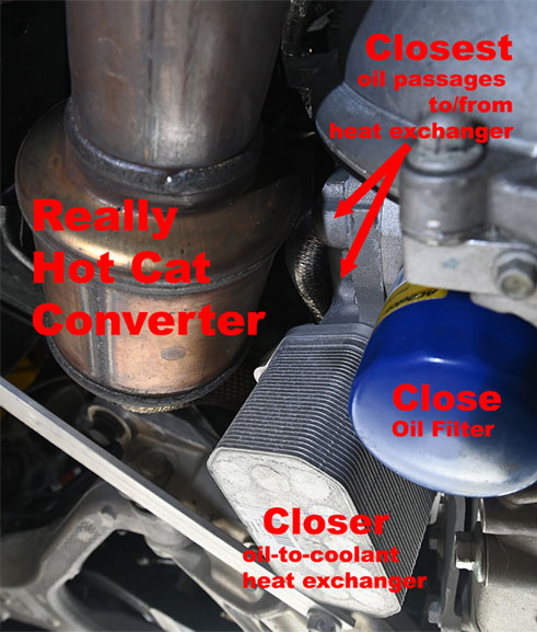
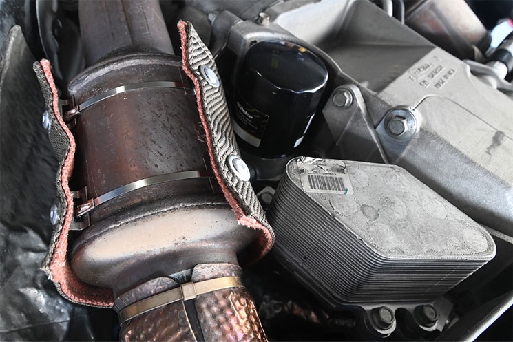
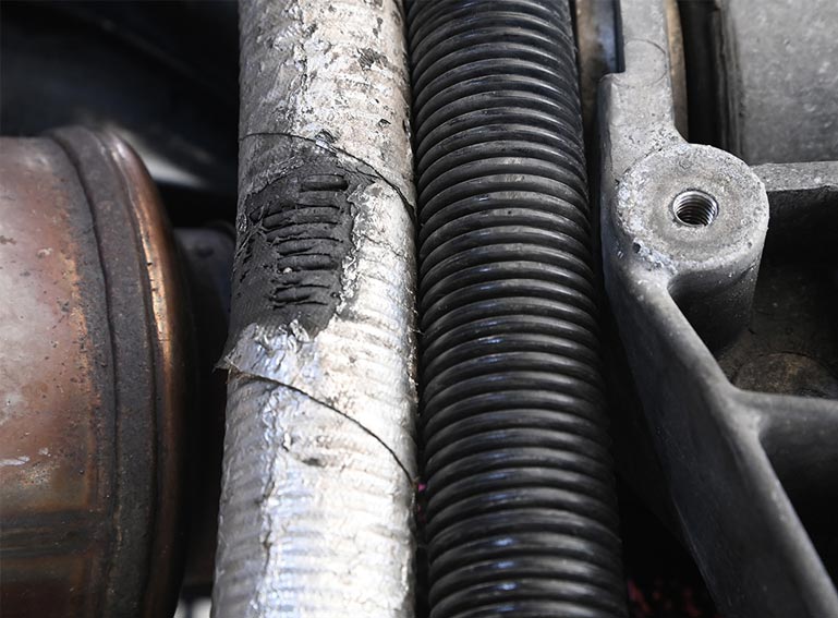
There are several ways heat gets into the engine oil: combustion in the cylinders, friction between moving engine parts and oil “windage” in the crankcase. All those happen inside the engine. Heat can also get into the oil from sources external to the engine like the exhaust system. Heat from the driver-side catalytic converter goes into the oil-to-coolant heat exchanger and its oil passages to-and-from the engine, as well as the oil filter. Heat from the passenger side exhaust, just past the exhaust manifold outlet, goes into the oil hoses which run between the engine and the dry sump tank, just above that pipe.
The specific Corvettes which can experience problem #1 are: those with oil-to-coolant heat exchangers, 11-13 ZO6s, 09-13 ZR1s and all C7s. As for problem #2, it can happen with 06-19 Corvettes having engines with dry sump oiling systems. Zip Products sells two different products made by Design Engineering (DEI) which will reduce the amount of heat radiated to the engine oil cooler, the oil filter or the oil hoses.

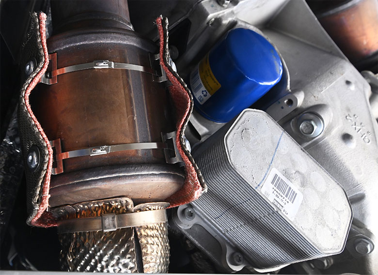
The first of these is a Catalytic Converter Heat Shield (PN EX-989). It attaches to the driver-side cat and reduces heat radiation to the heat exchanger assembly and the oil filter. This cat shield is a two-layer design. The outer is a woven fabric of volcanic basalt, or “lava rock”. This fabric is sometimes branded “Titanium” although it has no metallic content. To make it, volcanic basalt is melted, then extruded into thin fibers like the fibers used in glass-reinforced epoxy or “fiberglass”, then woven into fabric. The inner layer is an 89% silica material. Riveted to the inside of the shield are quarter-inch high, stainless steel stand-offs. Once installed, the shield has a three-inch gap at the bottom. The gap and the standoffs allow air to circulate around the cat to cool it. The shield is retained by 5×508-mm. (0.2×20-in) stainless steel ties which run through slots in the stand-offs.


01: The heat shield installation on the driver-side cat is the same for both C6 and C7. Putting on one of these shields can be a little tricky but read this through and you’ll get through it. Start by laying the shield out on a work surface with the eight metal stand-offs facing up. Grasp one of the stainless ties with the rounded side of the clasp pointed down, then slide it through one set of four standoffs. Do the same with the second tie. There will be two ties left over in case you damage one or both from the first two during installation.

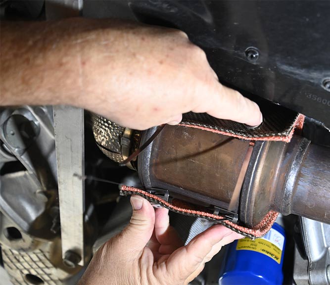
02: Get the car up on a lift or put some Billet Aluminum Jack Pucks in the front two frame holes and get the front end up on jack-stands. The first tricky part is getting the shield loosely around the cat without dislodging the ties from any the stand-offs. The next tricky part is the tight fit between the oil cooler assembly and the cat. Have patience and use finesse when pushing the shield in place and you’ll get it. The front top corner of the shield may snag the front oxygen sensor harness. Slip the fingers of one hand up around the front of the cat, then push the O2S wires around the edge of the shield while pushing on the shield with the other hand.

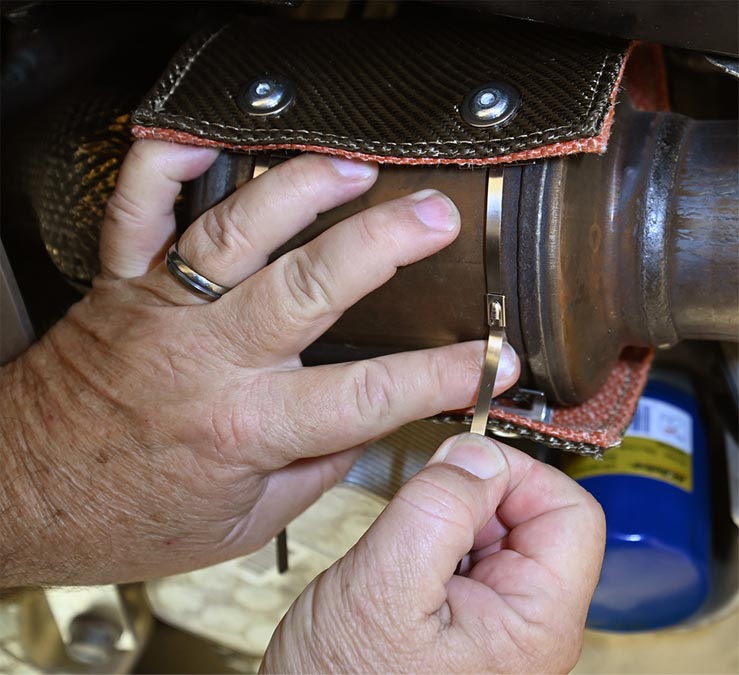
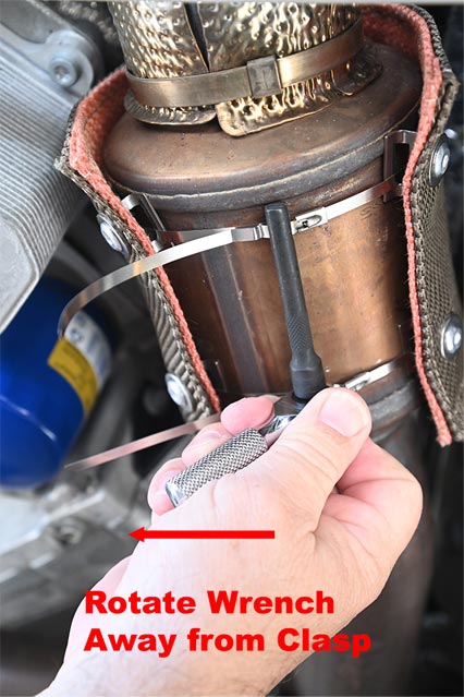


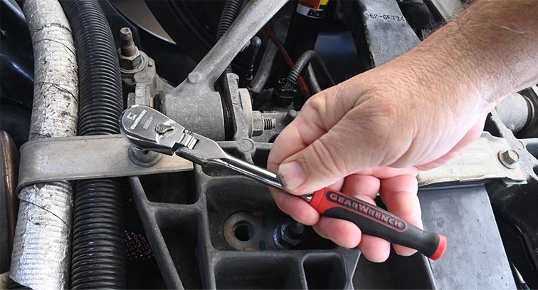
03: Once you have the shield loosely in place, push the end of each tie though the clasp and pull it hand tight. The sides of the tie can cut your fingers so either wear gloves, use a pair of pliers or pull the end–very carefully–bare handed. DEI includes one of their nifty “Locking Tie Tools” with each cat shield. Once you have the tie hand tight, about an 1/8-in past the clasp, engage the end of the tie with the slot in the tool. Attach a quarter inch drive ratchet. We used a 1/4-drive “stubby” ratchet because if you pull to hard, you damage the clasp and the stubby makes doing that more difficult. Rotate the tool away from the clasp until it’s tight.
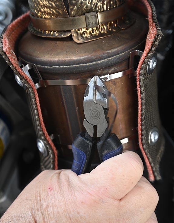
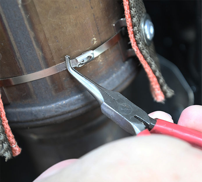
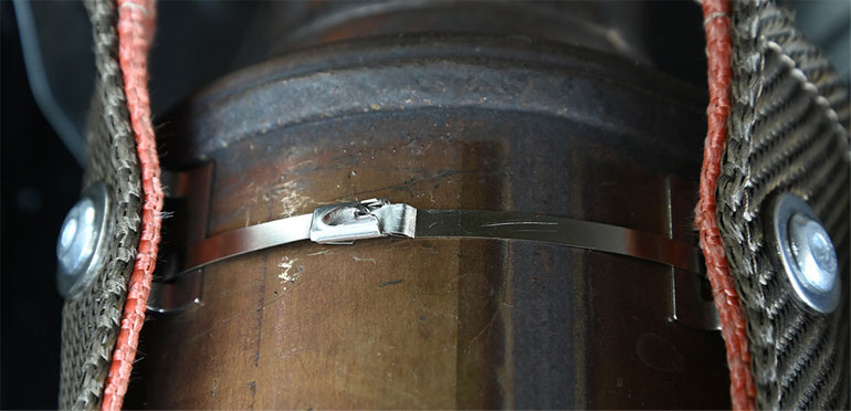
04: Use a pair of wire cutters or a small set of metal shears to cut remaining end of the tie. You’ll be left with a sharp edge that needs to be bent down or folded back over the clasp to prevent future injury to anyone working near the cat. I used a small pair of needle nose pliers with 90° jaws to bend the tip of the sharp edge towards the tie then pushed the rest of the remaining tie close to the cat.
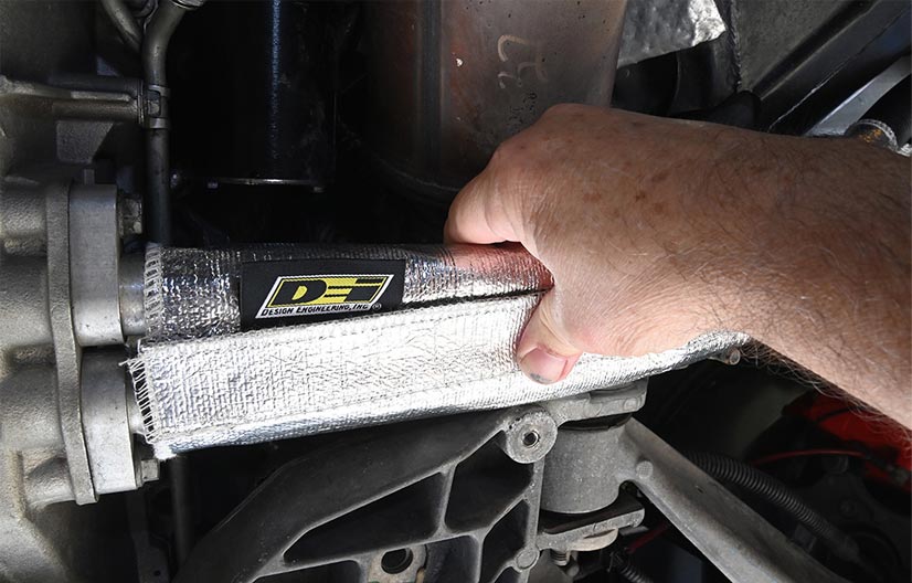
The second of the two Design Engineering heat control products is a thermally-reflective Oil Cooler Line Heat Shroud (PN EX-988) for the pair of oil hoses which run between the oil tank and the engine on C6es and C7s. This shroud is a high-temperature-resistant glass fiber material bonded to an aluminized fabric which reflects heat. DEI tells us the shroud can withstand up to 2000°F, way higher than the temperature in the vicinity of those oil lines.

05: To install the oil line shroud, wait until the engine cools, then raise the car as discussed previously. The first step is to remove the brace on all C7s that runs between the passenger side frame rail and the front suspension cradle. We also removed most of the screws holding the plastic shield under the oil tank and pulled a portion of the shield down and wired it out of the way in order to photograph the oil lines and the shroud installation. While pulling the shield back is not required, doing so makes it easier to put the shroud on, but it also increases the time necessary to do the installation because of the many screws and bolts to remove and replace.


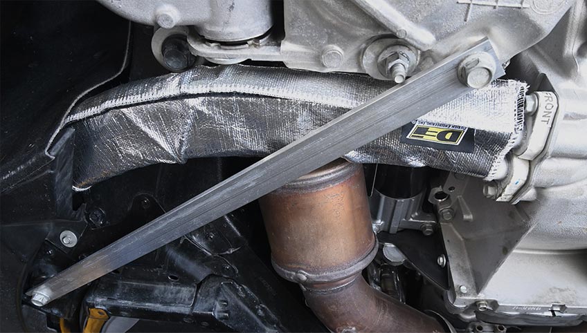
06: Start with the strips of hook-and-loop fastener facing down. Slide the shroud in place on the lines. If you left the oil tank shield in place, you may need to pull it down slightly, then push the shroud so it’s above the edge of the shield. Position the shroud so it is centered on the lines under the cat inlet. Then seal the hook/loop strips. Rotate the shroud such that the hook/loop strips face the rear of the car. Replace the suspension brace and torque the two bolts to 74 ft/lbs.
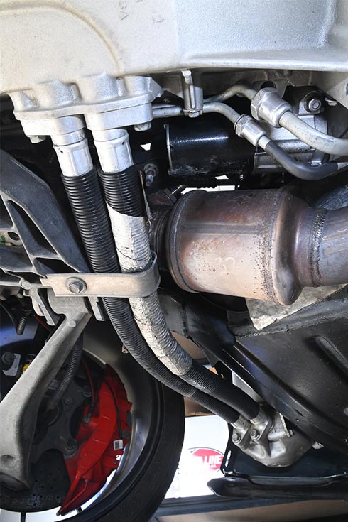

07: Installation of an oil line shroud on a C6 dry-sump car is like that of the C7 work, but there are differences. First, C6s have a bracket attached to passenger side of the front suspension cradle which retains the hoses. This bracket must be removed to install the shroud then reinstalled when you’re done. The C6 hoses are very close to the front suspension cradle. Again, we removed the plastic shield under the oil tank to photograph the process. On a normal C6 installation, leave the plastic shield in place. It’s smaller and shaped differently than the same part on a C7 so it doesn’t get in the way. Lastly, with a C6, rotate the oil line shroud so the hook/loop fastening strips face downward.
While we were installing the oil line shroud on a C6 ZO6, we found another application for a DEI cat shield: on the passenger-side cat to reduce the amount of heat radiated from the cat to the starter. The installation is virtually the same as for the driver-side cat, including using care to not foul the shield on the front oxygen sensor harness while pushing the shield in place. C7s do not need a shield on the passenger-side cat because the factory installed a rather large metal shield covering the starter and other components on the side of the engine.
Get the car back on the ground and go for a road test. You may find that for a short period of running time, cat shields may emit a small amount of smoke and an odor.
2006-2019 Corvette Exhaust Heat Control
Source: Zip Corvette Parts
8067 Fast Lane | Mechanicsville, VA 23111 | (800) 962-9632
Corvette Parts List Related to the Article: