

by Hib Halverson
Photography by Hib Halverson, Zip Corvette and GearWrench
Here at Zip’s corvettemagazine.com, one of our projects is a 1971 Coupe. Back in the mid-’90s, it was featured in the now-defunct Vette Magazine as the “Big-Block from Hell” project car. The powertrain is a 460-inch Big-Block and a six-speed manual transmission.
Lately, an intermittent problem has developed with the engine not returning to idle when the car is stopped or coasting in neutral. We tried different throttle return springs. While that influenced the problem, it didn’t solve it. Then we thought the electric choke on the car’s 850 CFM Holley four-barrel was malfunctioning, but that proved to be a dead end, too.
Finally, we focused on the car’s 54-year-old throttle cable. It also might be called an “accelerator cable” and the two terms are used interchangeably. Figuring that the cable was occasionally sticking in its housing, we decided to replace it.

Zip Corvette sells three reproduction cables. The one we chose fits 68-73 (PN CZ-773). The other two fit 74 only (CZ-774) and 75-81 (CZ-775). We also ordered a 68-82 Corvette Accelerator Cable Retainer and a 68-73 Corvette Accelerator Cable Clamp. Currently, reproduction accelerator cables for 1982s are not available. Some used Corvette parts vendors may sell them. Also, 82 throttle cables sometimes appear on eBay.
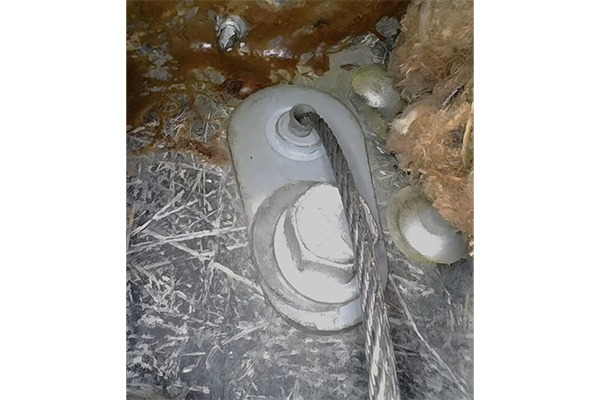
Working under the instrument panel of a C3 Corvette is never easy, but changing the accelerator cable is particularly difficult because of where the cable comes through the firewall–a confined space way high up behind the instrument panel. This space is so difficult to access that some of the photos were shot with a borescope.

C3 throttle cable replacement requires removing bolts from the interior side of the firewall; a specific assortment of tools is required. You need a ¼ inch drive ratchet, a 12 to 14-inch, ¼-drive extension, and two ¼-drive swivel sockets, ⅜-in and 7/16-in.

You’ll want an LED work light, such as the Gear Wrench GWFL 85 or GWFL105. Either is ideal for working under the IP of a C3 because they’re slim and easy to handle. Both use lithium-ion batteries. They have rotating flex heads to direct light. Both have three white light modes: “spotlight”, “floodlight”, and “tip light”. They also have a “red light” mode, which is the most intriguing feature of these products. For this article, we interviewed Jarrett Wolf, GearWrench Director of Product Management
“The science behind (this feature) is how (our eyes) process different visible light wavelengths,” Wolf told CorvetteMagazine.com. “Red light has the longest wavelength of visible colors. The eye’s rods, responsible for low-light and peripheral vision, are less sensitive to red. Because rods do not respond strongly to red, a red light prevents the eye from being ‘blinded’ or fatigued by white light. This allows users’ eyesight to adjust more quickly when looking between the light and darker areas of the workspace.
Additionally, red light sharpens the perception of edges and small details by minimizing blue light scatter and glare,” Wolf continued. “This creates greater visual contrast, making it easier to spot small components, read markings, and distinguish surfaces in tight or shadowed spaces.”
During product development, GearWrench designers studied how people use lights in automotive work. They are often used for extended periods in dark or confined spaces. GearWrench determined that adding a red mode would reduce eye strain and improve clarity where precision matters most.
The bottom of each has a magnetic base, a hook for hanging, and a clamp that spreads up to two inches. Both have a small magnet next to the tip light, which is great for picking up small ferrous metal parts. Online reviewers give these lights 4.8 out of five, so we ordered both and after using them for the several hours required to replace the accelerator cable, we believe the 4.8 review average is justified. For us, standout features were battery run time longer than other work lights we’ve used and the red light mode. Both are good work lights, but for this job, the GWFL 85 was our favorite because of its shorter length.
While these lights come with a charge cable, they do not come with a charger. GearWrench recommends a UL- or SCA-listed, “Class 2” charger that produces 10 watts at 5 volts and has a USB-A connection. An example of this is the now-discontinued Apple A1385 “Travel Charger,” many of which can be found on eBay. There are other brands of 10W5V chargers available. Some are UL/CSA-listed, but some are not. HD chargers with USB-A outputs are available from Motorola (20W) and Tripp Lite (14W) and cost $22.00 to $28.50.

Before starting the cable replacement, to prevent damage from inadvertent grounding of B+ wiring under the IP, disconnect the negative battery cable. Begin work by removing two bolts that hold the accelerator pedal assembly to the firewall. This assembly has two parts: the pedal rod sandwiched between them, the pedal rod support, and the pedal rod support plate or bracket. On a late-69 to 76 stick-shift car, the two bolts, shown in this image, hold a small, square plate. Remove the bolts and the plate. If the car is a ’68 or early ’69, the pedal assembly still bolts to the firewall and connects to the cable at the top, but its design is more complex. The pedal rod support does not disassemble as it does on late-69 and up C3s. Remove the two bolts from the pivot, and the pedal comes loose.

From this point on, if you are big or tall, remove the driver’s seat so you can lie on the floor with your head under the IP. Our ’71 hot rod has racing seats bolted to the floor that are easy to remove. Most other folks will have stock or other aftermarket seats, so the seat removal procedure may vary. See the service manual for your model year and seat type or, if you have aftermarket seats, the seat maker’s documentation.

If you are big or tall and your car lacks a tilt steering wheel, the job may be easier if you remove the steering wheel. That requires a steering wheel puller, available from auto parts stores or online vendors. Pop off the horn button cap and remove the horn button parts, and remove the steering wheel nut. Install the puller, then turn the center bolt to remove the wheel.

Once you’re in position, you might be uncomfortable because the footwell and floor under the seat are different heights.

You can reduce that discomfort by rolling up several old towels to make a pillow for your head and neck. Place them in the footwell ahead of where the floor curves up to the seat mounting surface.
70-76 C3’s with automatic transmissions, and all 77-82 C3’s, have a three-bolt bracket retaining the accelerator pedal. On 70-76 automatics, a three-hole extension from this bracket holds a throttle switch for the THM400 automatic. On some late C3s, this switch also controls the cold air hood solenoid. Disconnect the wires to the switch. Not only does this bracket retain the accelerator pedal rod, but the top of it bolts high on the inside of the firewall.

Set up your work light, get under the IP, then, using the tool combination discussed earlier, remove the bolt at the top of the inside of the firewall. On a 68-73 with a manual transmission, that bolt retains the pedal end of the accelerator cable. On a 70-73 automatic car, that bolt retains both the pedal end of the throttle cable and the top of the accelerator support bracket. On 74-82, that bolt retains the top part of the accelerator pedal rod bracket. That bracket must be removed before the accelerator cable retainer can be unlocked and pushed through the firewall towards the engine.
With 74-82, unlock the retainer by squeezing the tabs with slip joint pliers, such as the 8-inch, GearWrench “PitBull” Tongue and Groove pliers (PN 82169C) and pushing the retainer partway through the firewall. If the car is a 68-74, pop the end of the cable off the carburetor. Sometimes that can be done with just your fingers; however, it can be so tight, that you need to pry it off with a flat-blade screwdriver.

On 68-73, remove the bolt holding the metal end of the cable housing to the bracket attached to the carburetor. If the car is a 74-81, remove the metal accelerator cable end retainer, then remove the cable end from the carburetor’s throttle lever. If the car is an ’82, remove the cable end retainer and cable end from the throttle lever of the driver’s side throttle body. Finally, remove the cable from the cable bracket on the carb or T.B.

On a 74-82, working under the IP while using a work light to see, push the pedal arm forward, then pull the cable end out of the cable retainer on the pedal arm. Push the plastic cable retainer out of the arm. Line up the gap in the retainer with the cable, then slide the retainer off the cable.

On 68-73, push the cable from the engine towards and through the firewall into the interior. On 74-82, remove the cable by pulling it through the hole in the firewall and out.

On 68-73, from under the IP, reach up and pull the accelerator pedal and cable down and out, being careful not to snag any wiring. Set the parts on your workbench.

Separate the old 68-73 cable from the accelerator pedal by pulling the cable end away from the hole at the top of the pedal arm. Push the plastic retainer out of the pedal arm. Line up the gap in the retainer with the cable, then pull the retainer off the cable. Some retainers will not be easy to get off the cable. If that’s the case with your project, spread the retainer slightly with a small screwdriver.

On 68-73 push the pedal end of a reproduction, 68-73 Corvette Accelerator Cable through the hole in the pedal, then push a new 68-82 Corvette Accelerator Cable Retainer over the cable, and then snap the retainer into the pedal arm.

We dabbed some RTV sealer on the side of the 68-73 cable’s mounting plate that faces the firewall, then, once again working under the IP with our GearWrench GWFL 85 lighting the way, we carefully guided the engine end of the cable up under the IP and through the hole in the firewall.

On our ’71 project car, we alternatively pushed from underneath the IP and pulled on the engine end of the cable until the mounting end of the cable assembly mounting plate was flat against the inside of the firewall.

If you have “pixie fingers,” you can start the 68-73 cable’s retaining bolt into the bolt hole and get it finger-tight. Most will find that impossible, so smear Vaseline on the bolt head to retain it in the ¼-drive, ⅜ swivel socket. Attach the long extension and use that setup to insert the bolt. Use the swivel, the long extension, and the 1/4-drive ratchet to screw the bolt through the 68-73 cable’s mounting plate and into the firewall. Temporarily, leave the pedal assembly loose.
On a 74-82, from the engine compartment, push the cable end and cable retainer through the square hole in the firewall. Continue to push the cable until the rear cable retainer snaps into place on the firewall

Confirm it’s locked by using your work light to see the interior side of the firewall and verify the retainer’s locking tabs have expanded over the edges of the hole in the firewall. Connect the cable to the pedal arm by pushing a new 68-82 Corvette Accelerator Cable Retainer onto the cable, then snap the retainer into the top of the pedal arm.

For late-69-82, clean the accelerator pivot and lubricate it. Put the pivot in place on the firewall, and push the accelerator pedal assembly into the pivot.

On 68-early 69 (not shown), reinstall the pedal assembly by bolting the pivot to the firewall. On late 69-73 manual trans cars, reinstall the cover plate and the two bolts.
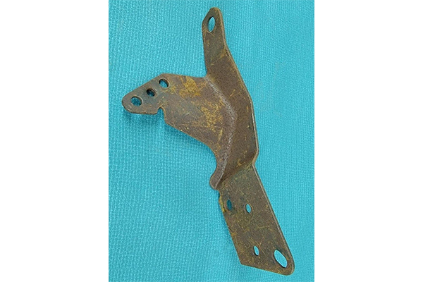
On 70-74 automatics and all 75-82’s (not shown), reinstall the 3-bolt bracket. With that, thankfully, you are done working under the instrument panel.

On 68-74, push the end of the cable onto the ball stud on the carburetor’s throttle lever.

If the car is a 68-73, install Zip’s new 68-73 Corvette Accelerator Cable Clamp on the carburetor’s accelerator cable mount. On 74-82, push the cable’s forward retainer through the slot on the cable retainer bracket on the carburetor or throttle body.

With 75-82, the stud in the throttle arm of the carburetor or primary throttle body should be lubricated. Then, push the end of the cable over the stud and replace the throttle cable retainer.
Visually inspect the cable operation. On 68-81, make sure the choke is not enabled, then with all C3s verify the throttle lever is at curb idle. Some engines have “anti-dieseling solenoids,” and, if so equipped, that solenoid must not be enabled for this step. The throttle lever needs to touch the idle screw. Next, pull the cable all the way into the housing and verify the carburetor or throttle body is at wide open throttle.

Our project car’s 850 Holley is on an Edelbrock Performer RPM manifold, so the cable housing mounting location in space was different than stock. Our check of curb idle was ok, but when we pulled the cable all the way back, the 850’s secondaries were not wide open.
To fix that problem, we moved the cable housing’s metal end in the cable bracket to a point where, at one end of the travel, the 850 was at curb idle, and at the other end, the secondaries were wide open. We marked the position of the cable in the clamp. We also decided to replace the bolt that came with the clamp with our different bolt that had an integral lock washer.
To finish off this project, we reinstalled the driver’s seat and put the steering wheel back in place. Then went out for a road test!