

by John Pfanstiehl
Installing an electric fan assembly to cool the radiator in place of the mechanical fan has several advantages, including increased room in the engine compartment. That makes future removal of the radiator or the fan shroud and motors much easier. Electric fans also promise increased cooling capacity at idle and low speeds. The fans may not even turn on when there is sufficient air flow through the radiator while driving down the road and that helps gas mileage slightly. The horsepower drag of the mechanical fan is eliminated too. The gain can be in the neighborhood of 15 horsepower at 5,000 rpm which is a big deal for those who care.
The flip side is that electric fans are noisier when on and they have more components that could fail. When their fuse, relay, motor, wiring or sensor fails, the fans provide no cooling. The standard mechanical fan rarely fails and strands a car. Also, a higher amp alternator may be needed if the fans run a lot.
However, dual electric fans reduce the potential problem of part failure because there are two of every part except the temperature sensor. In a standard installation there is only one sensor but if that fails to close, the sensor’s wire can simply be grounded to get the car home.
The standard installation has both fans running at the same time; they are switched on when the one temperature sensor closes. An option is to install a sensor with a lower temperature rating for one fan. Then the sensor with the lower temperature rating will come on first – and much of the time only that one fan will need to be running. This is a consideration for C3’s that have lower amp alternators. The alternator might not be able to keep up with two fans running when idling in traffic for a long time.
The current draw of one fan was 17 amps and the other was 19 amps. The instructions supplied by the fan manufacturer said to use a 15 or 20 amp fuse for each fan. However, the kit included only a 30 amp and 40 amp fuse. Install the 30 amp fuses and keep the 40 amp fuses in the glove box.
The sensors close the relays which turn on power to the fans. The 195F sensor is supposed to turn the fan on when the coolant temperature reaches 195F and then turn the fan off when the coolant temperature falls 20 degrees to about 175F. (On the two sensors we tested, these values were only approximate.) Note: in an engine that has a 180F thermostat, this single sensor system results in both fans being on all the time if the engine temperature rises to 195F.
It is still a good idea to have a thermostat in the engine even though the sensors turn the fans on and off in a set temperature range. For one thing, without a thermostat, the coolant may run too fast through the radiator to be efficient. Also on a cold day, the engine might not heat up sufficiently when driving.
The dual fan kit comes with two wiring harnesses, two relays, fuses and one sensor. However the manufacturer’s instruction sheet says that cars with air conditioning also need to get a third harness kit with another harness and relay. As an alternative, this Tech Article shows an easy installation of an inexpensive relay for A/C cars.
A very simple alternative to using the two wiring harnesses, two relays, two fuses and one sensor is to just run two or three wires (one with a fuse or fusible link) into the passenger compartment and use one (or two) 20 amp toggles switches. The driver then turns the fans on if the coolant temperature begins to rise too high.
Zip Corvette offers the 1968-1982 SPAL Dual 11in Electric Fan Package & Shroud for C3s. The normal installation of this package’s two harnesses, two relays and two fuses is detailed here. Then this Tech Article goes a bit further showing the custom installation of two sensors, the 185F and a 195F models.
Notes: Information on C3 radiator removal and installation is detailed in Zip Corvette’s Tech Articles that are coming soon. Also for C3s converted to a LS engine, a combination electric fan assembly and radiator is available 1973-1976 350/454 w/4-spd LS Conversion Direct Fit Aluminum Radiator & Fan Combo.

01: Remove the protective plastic coating from the aluminum fan shroud support brackets. If desired, prep both of these brackets, apply a primer such as Zip Corvette’s Green Zinc Primer Paint ZMG-100 and topcoat with a semi-gloss or satin black paint to better match the black plastic shroud that holds the electric fans.
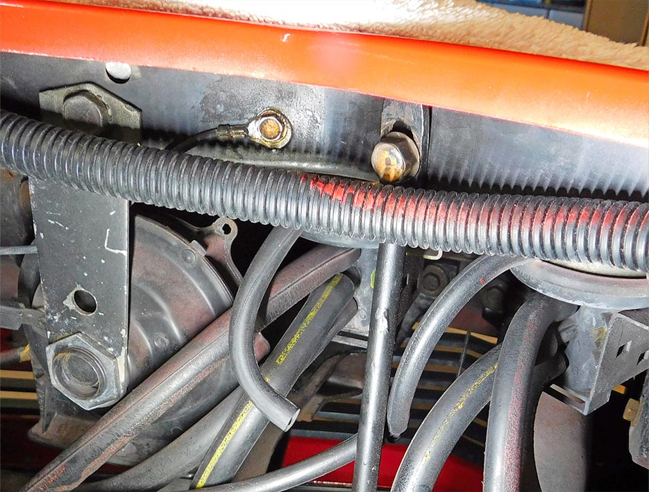
02: A convenient place to ground the radiator is near the horns. There is no need to ground the radiator if the temperature sensor is not located in the radiator.
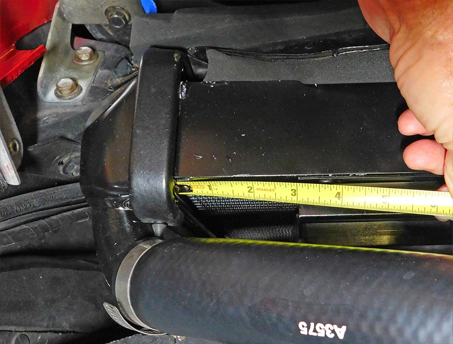
03: The shroud of this dual fan assembly fits best when mounted a bit over 3-inches from the left hand radiator tank weld on this 1973 Corvette. Note that the shroud was not centered on the radiator – it was about an inch from the radiator weld on the right side.

04: The fan shroud of the dual fan assembly just fits between the upper a-arms. This shows how close it is on the driver’s side.
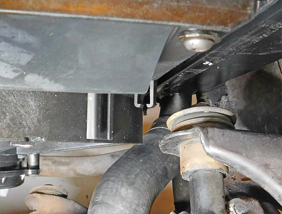
05: The right side of the fan shroud is equally close to the passenger side upper a-arm and is also close to the lower radiator hose. When everything is installed, make sure the rear edge of the fan shroud doesn’t rub against the hose.
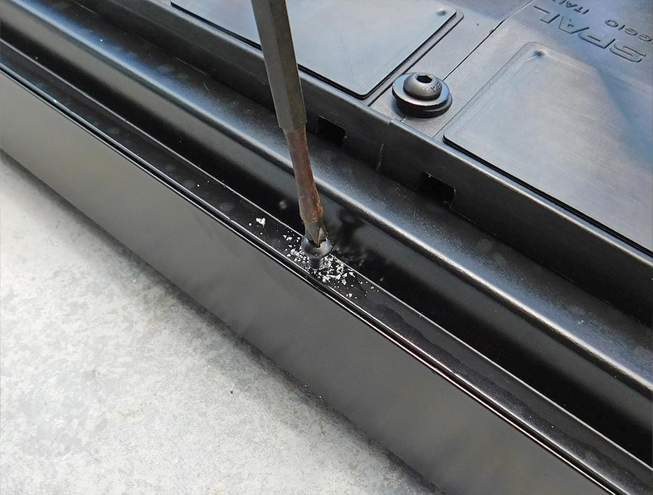
06: The six self-taping screws drill easily into the upper and lower channels on the aluminum radiator. Note: before drilling these attachment holes, the best alignment needs to be determined for the shroud.
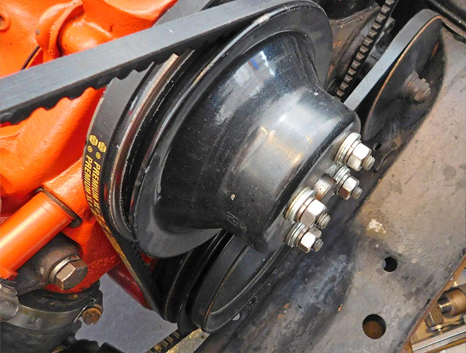
07: Remove the fan. Then reinstall the original bolts and lock washers adding 5/16-inch washers or spacers. Alternately, remove the studs one at a time and replace them with a ½-inch long 5/16-24 (fine thread) bolt and lock washer.

08: Remove a plug from the intake manifold if that location is a convenient place to install the temperature sensor. Tip: if the plug is seized, carefully use a propane torch to heat the manifold around it and apply penetrant to help break the plug loose.

09: If there is a plug in the rear of the right cylinder head, this can be removed to provide an alternate location for the temperature sensor or it can be a second location if two sensors are used. Note: a Direct Fit aluminum radiator may have a sensor location.

10: One sensor is included with the dual fan kit; it turns the fan on when the coolant temperature rises to 195F. Sensors that turn the fan on at 185F are easily found online. This 185F SPAL sensor looks identical to the one included in the kit. Both were made in Mexico.

11: Testing the sensors revealed that the stated temperatures are approximate. The sensor marked 195F turned on at 200F and turned off at 185F. The sensor marked 185F turned on at 192F and turned off at 175F. It is likely that other sensors have some variance also.

12: Apply anti-seize compound on the threads to avoid removal problems in the future. Because the sensors need to be grounded, it is recommended not to use Teflon tape. The pipe thread hole in the cylinder head was larger so it required use of the adapter included in the kit.

13: Two wiring harness boxes come with the dual fan kit. They look the same at first but one kit has a sensor and adapter.

14: Prepare the inline fuse by cutting the wire loop. Attach the eyelet terminal to one side and attach the yellow wire from the relay to the other side. If the relay is being mounted close to the power source, the leads off the inline fuse can be short as shown here.

15: Plug the green 30 amp fuse into the inline fuse holder. Although the included instruction sheet says to use a 15 amp or 20 amp fuse, the kit comes with a 30 amp and a 40 amp fuse. The fans in this kit drew 17 and 19 amps respectively so a 30 amp fuse provides an appropriate safety factor.

16: The two relays were installed next to the horn relay on the left inner fender. The horn relay has a stud which is a connection point for 12 volt power on Corvettes and is connected to the alternator output by a relatively short wire.
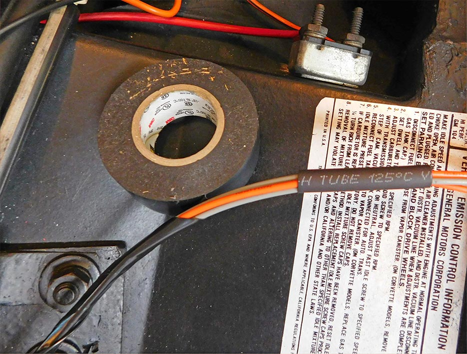
17: Run the small gray wires to the sensor(s) and the small orange wires can be run to the positive side of the ignition coil or any circuit turned on by the ignition switch. Wrap these wires with 3M electrical tape to make them fit in with the factory wiring. Tip: heat shrink tubing helps keep the wires together while running or taping them.

18: Exit the small gray relay wire(s) from the hand-made harness to run to the sensor. In this installation, it ran down the right side of the intake manifold to connect with the sensor on the front of the manifold.

19: The small gray wires from the other relay continued from the harness to connect to the temperature sensor in head in this installation. If only one sensor is used, the two gray wires can be connected together at any point and just one wire connected to the single sensor, or both wires can be run to the sensor.

20: Apply dielectric grease to the male and female connectors of the motor harnesses. This is not essential but it will reduce the likelihood of corrosion on these connectors since they are located low in the engine compartment and therefore exposed to the elements.

21: Run the two fan power wires alongside each other and connect them to the red wires from the relays. Connectors and heat shrink tubing help to make a clean looking installation.

22: Attach the fan ground wires to a convenient location. The frame bolt for the brake line bracket was nearby on this car.

23: The newly made fan control wiring harness looks good and fits in well with the existing wiring harnesses and hoses. It contains the gray wires that go to the sensors and the orange wires that go to a circuit turned on by the ignition switch.

24: Run the harness that delivers the power to the fans alongside the original wiring harness and vacuum hoses for a good looking installation.

25: The instruction sheet included with the dual fan assembly says to buy another SPAL wiring harness with relay to force the fans to turn on with the air conditioning. Another way of accomplishing this is to use any simple four or five terminal relay connected with a few small wires. Cars without air conditioning do not need the additional relay.

26: The gray wire of the additional relay is quick-connected to a temperature sensor. The jumpered ground wire is connected to the black ground wire on the blower relay. The wire that controls the relay is connected to the (green) compressor clutch power wire. Zip tie the relay out of the way and the installation of the relay on A/C cars is finished.
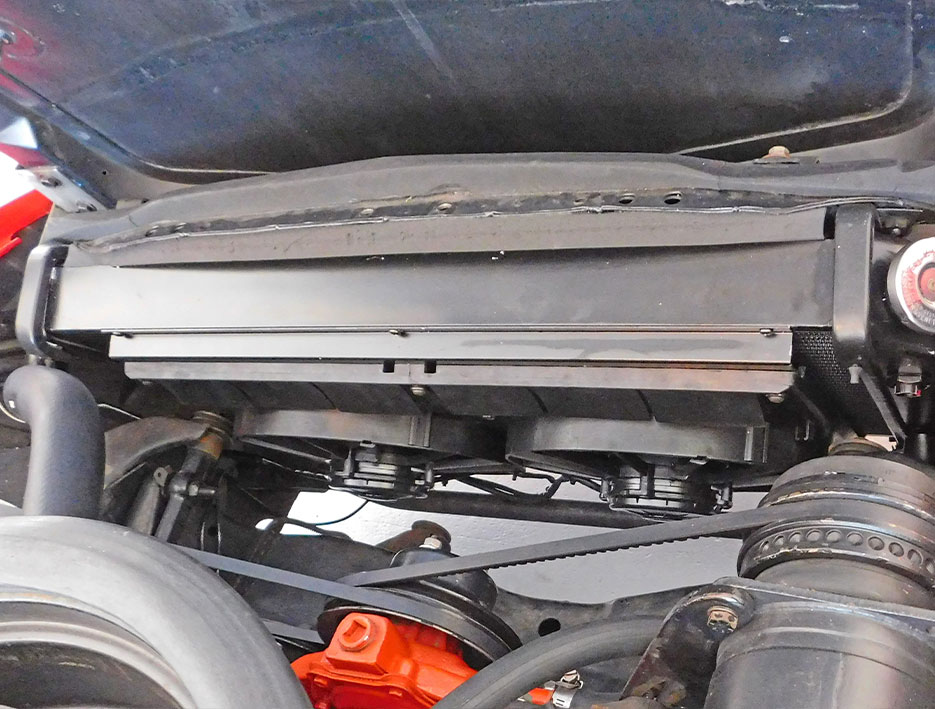
27: The dual electric fan really opens up the front of the engine compartment. There’s much more working room for any future tasks on the front of the engine, such as water pump, front main seal or lower radiator hose replacement.
1968-1982 Corvette Electric Fan Installation
Source: Zip Corvette Parts
8067 Fast Lane | Mechanicsville, VA 23111 | (800) 962-9632
Corvette Parts List Related to Article:
- 1968-1982 SPAL Dual 11in Electric Fan Package & Shroud
- 1969-1972 427/454 4-spd LS Conversion Direct Fit Aluminum Radiator & Fan Combo
- 1969-1972 427/454 Auto LS Conversion Direct Fit Aluminum Radiator & Fan Combo
- 1969-1972 350 4-spd w/AC or LT1 LS Conversion Direct Fit Aluminum Radiator & Fan Combo
- 1969-1972 350 Auto LS Conversion Direct Fit Aluminum Radiator & Fan Combo
- 1969-1972 350 4-spd w/AC or LT1 Direct Fit Aluminum Radiator & Fan Combo
- 1969-1972 350 w/Auto Direct Fit Aluminum Radiator & Fan Combo
- 1969-1972 427/454 w/4-spd Direct Fit Aluminum Radiator & Fan Combo
- 1969-1972 427/454 w/Auto Direct Fit Aluminum Radiator & Fan Combo
- 1973-1976 350/454 w/4-spd Direct Fit Aluminum Radiator & Fan Combo
- 1977-1982 w/Auto Direct Fit Aluminum Radiator & Fan Combo
- 1973-1976 350/454 w/4-spd LS Conversion Direct Fit Aluminum Radiator & Fan Comb
- 1973-1976 350/454 w/Auto LS Conversion Direct Fit Aluminum Radiator & Fan Combo
- 1977-1981 w/4-spd LS Conversion Direct Fit Aluminum Radiator & Fan Combo
- 1977-1982 w/Auto LS Conversion Direct Fit Aluminum Radiator & Fan Combo
- 1973-1976 350/454 w/Auto Direct Fit Aluminum Radiator & Fan Combo
- 1977-1981 w/4-spd Direct Fit Aluminum Radiator & Fan Combo
- 12oz Green Zinc Primer Paint
- Shop/Service Manuals
A good alternative is to connect the relay power wires(s) to the yellow (windshield wiper/washer) or tan (if the car has time delay relays or such). These circuits are OFF when the ignition switch is in the Start position, therefore the fans will be OFF resulting in less voltage drop at the starter solenoid. Also be aware the electric fan(s) must be ON when the A/C is on at idle or low speeds.
Great Article!
Enjoy reading your article. I have a question about the last part where you retrieved a 4 pin relay instead of purchased another Spal relay. Can you please identify what PIN numbers on relay you connected those wires to? I’m currently at that point- need to do last part with relay and I’m having trouble with it and want to be sure I’m doing that part right. The dual fan works but I need AC to kick on once I Connect it properly. I trying it with a 5 pin but not have any luck.
please advise and many thanks!