
When GM introduced the LT1 engine in 1992, Corvette owners got a completely new ignition system. The Optispark distributor was a major departure from the traditional top-mounted HEI and points distributors GM had used for decades.
Instead of a mechanical trigger, the Optispark uses an optical sensor to determine ignition timing. The distributor is mounted on the front of the engine, beneath the water pump and behind the harmonic balancer. While the design delivers extremely accurate timing, it also places the distributor in a challenging environment.
Over time, heat, moisture, ozone buildup, and oil/coolant leaks from aging seals can lead to corrosion inside the unit. When this happens, the symptoms usually appear as intermittent misfires, rough running, or even a no-start condition.
Because replacing the Optispark requires removing the water pump and crank pulley, it’s a fairly involved job. For that reason, it’s important to confirm the distributor is actually the problem before beginning the repair.
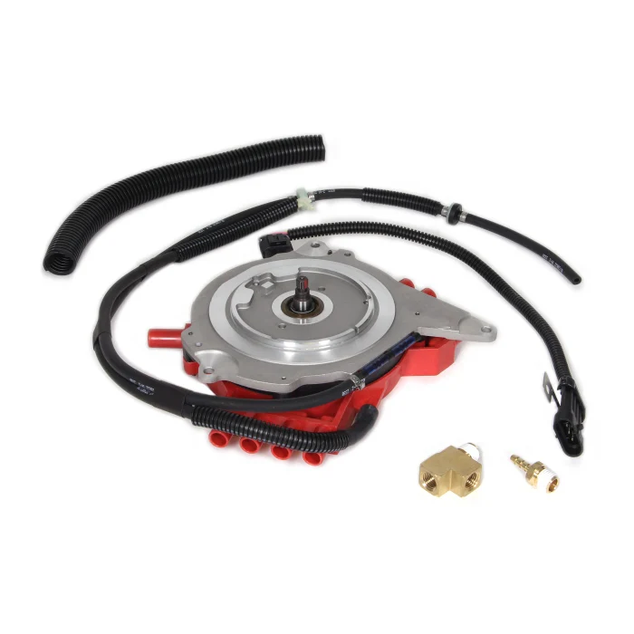
When it is time to replace the Optispark, installing a high-quality unit is critical. The Petris Optispark distributor is widely regarded as the gold standard, featuring the Mitsubishi-grade optical trigger used in premium units. Cheaper replacement distributors often fail prematurely—or may not function properly right out of the box.
Since the water pump must be removed to access the distributor, this is also the perfect time to replace the water pump and spark plug wires.
With the right parts and a free afternoon, this is a job most Corvette owners can complete in their own garage.
Getting Started
The Optispark can be accessed from the top of the engine bay. While the job can be done on the ground, placing the Corvette on ramps will give you a bit more working room and make plug wire routing easier, especially on the driver’s side.
Start by disconnecting the negative battery cable.
Next disconnect the following electrical connectors:
-
- Idle Air Control (IAC) harness at the bottom of the throttle body
- Coolant temperature sensor on the front of the water pump
- Intake air temperature sensor on the intake duct
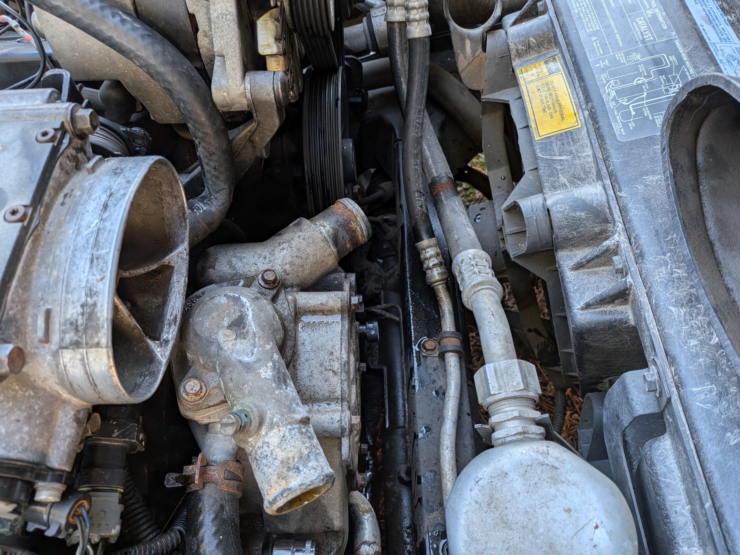
Loosen the clamp on the intake boot and remove the rubber duct connecting the air filter housing to the throttle body.
Drain the Cooling System
Before removing the water pump, the cooling system needs to be drained.
Open the drain port located on the lower right side of the radiator. Remove the radiator cap from the surge tank and open the bleed screw on the thermostat housing to allow the system to drain quickly and completely.
Once drained, remove the upper and lower radiator hoses along with the heater hoses connected to the water pump. Remove the thermostat housing and thermostat.
This is a good opportunity to inspect radiator and heater hoses and replace them if needed. LT1 engines operate at temperatures between 180°F and 220°F and approximately 16 PSI of cooling system pressure, so hose condition is important.
Removing the Water Pump
Six bolts hold the water pump in place:
-
- Four long bolts on the pump flanges
-
- One outer bolt on the passenger side
-
- One outer bolt on the driver side
The driver-side outer bolt sits partially behind the power steering pulley. A wobble socket makes this bolt much easier to access.
Unlike many engines, the LT1 water pump is not belt driven. Instead, it is driven by a shaft connected to the camshaft and engages a splined receiver in the timing cover.
Once the bolts are removed, pull the pump straight forward from the engine. Avoid rocking it excessively while removing it.
Removing the Serpentine Belt and Crank Pulley
Rotate the belt tensioner to release tension and remove the serpentine belt. Inspect the belt for cracks or wear while it is off.
Two styles of belts were used on LT1 engines—one with grooves on a single side and another with grooves on both sides—so verify the correct replacement if needed.
Next remove the crank pulley. Three bolts secure the pulley to the Y-shaped crank hub.
You may need to hold the pulley in place with a prybar, screwdriver or ratchet while loosening the bolts. Once removed, lightly tap the pulley if necessary to free it from the hub.
Rotate the engine using the center crank bolt so the hub does not block access to the Optispark.
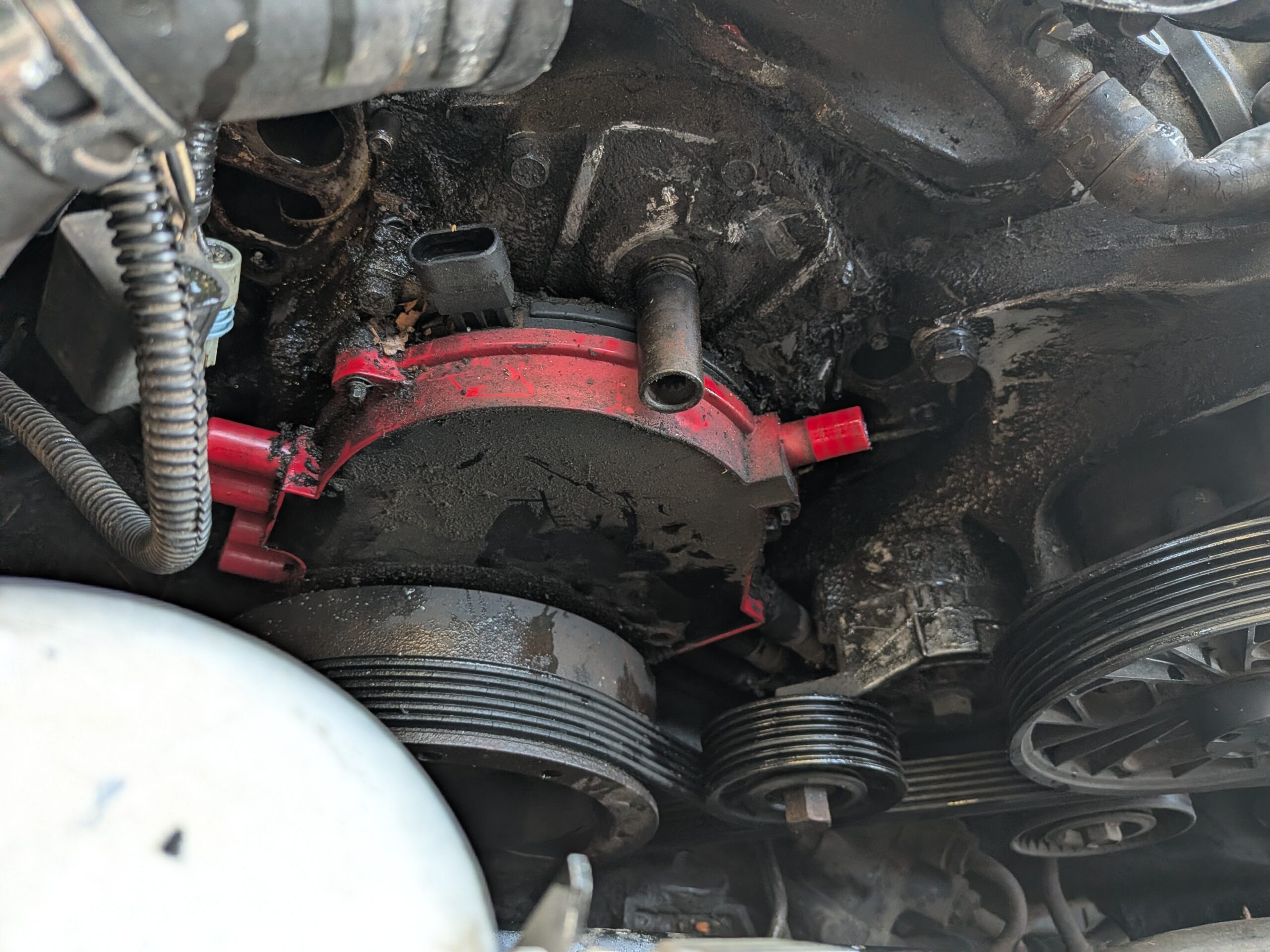
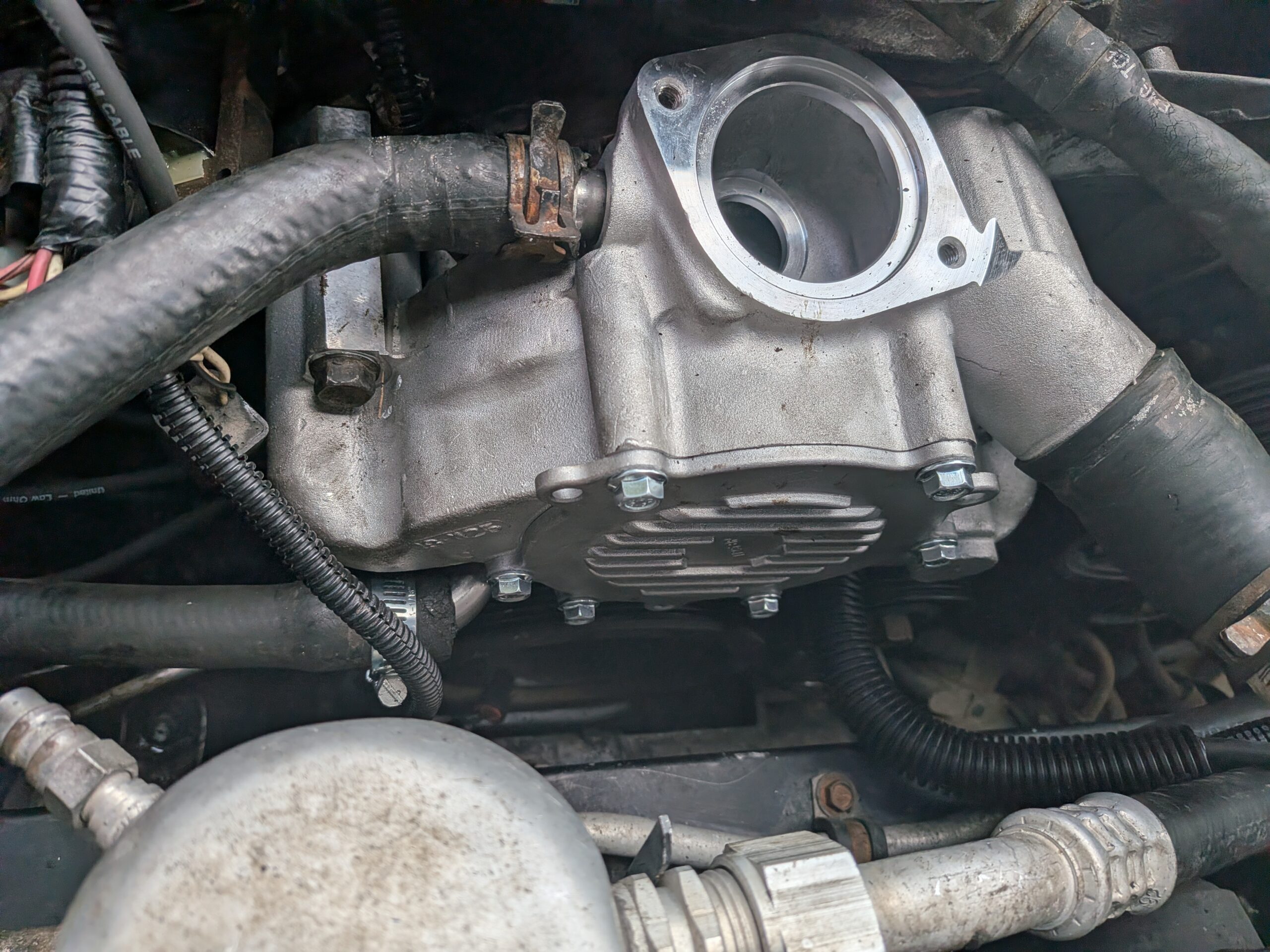
Removing the Optispark Distributor
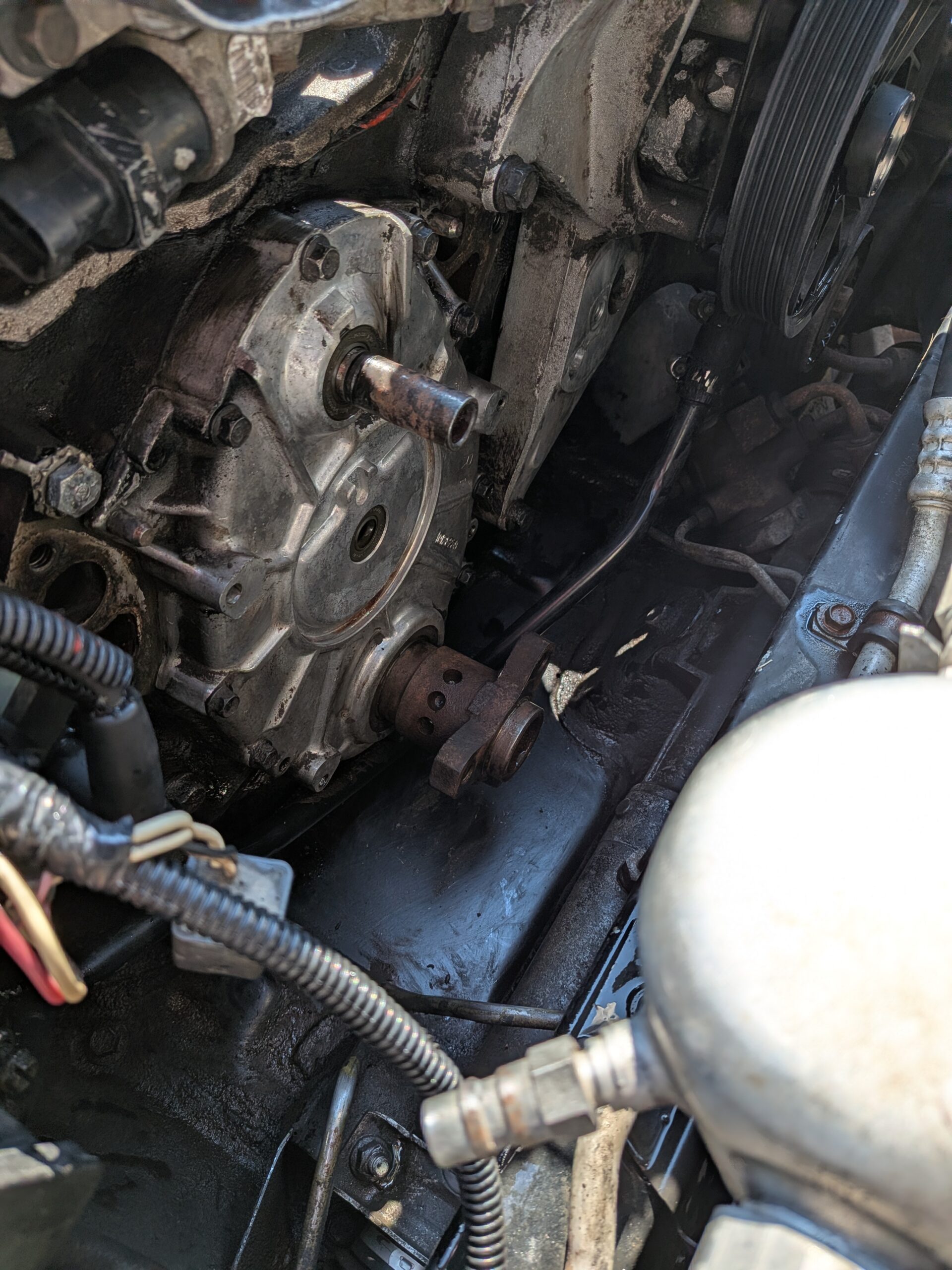
Remove the spark plug wires and coil wire. If you plan to reuse them, mark their locations before removal.
Disconnect the Optispark harness and remove it completely. The Petris replacement distributor includes a new harness.
Three bolts secure the distributor to the timing cover—two on the passenger side and one on the driver side. Remove these bolts and carefully pull the Optispark forward away from the engine.
Take note of the orientation of the wide alignment spline before removing the distributor.
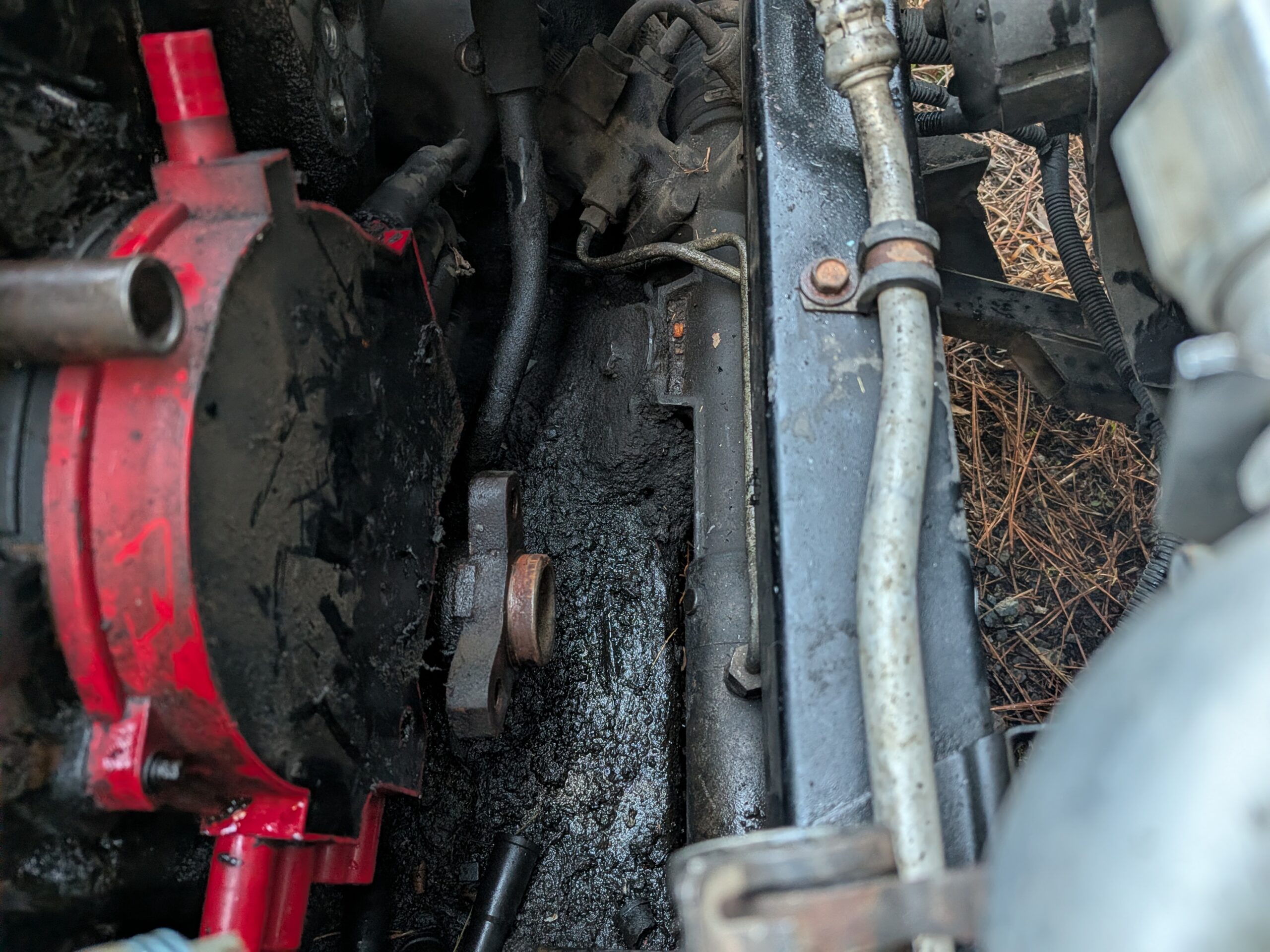
With the Optispark removed, you now have clear access to the timing cover. This is a good time to clean the area and inspect for any leaking seals.
If the front main seal or timing cover shows signs of leakage, it can also be replaced at this stage.
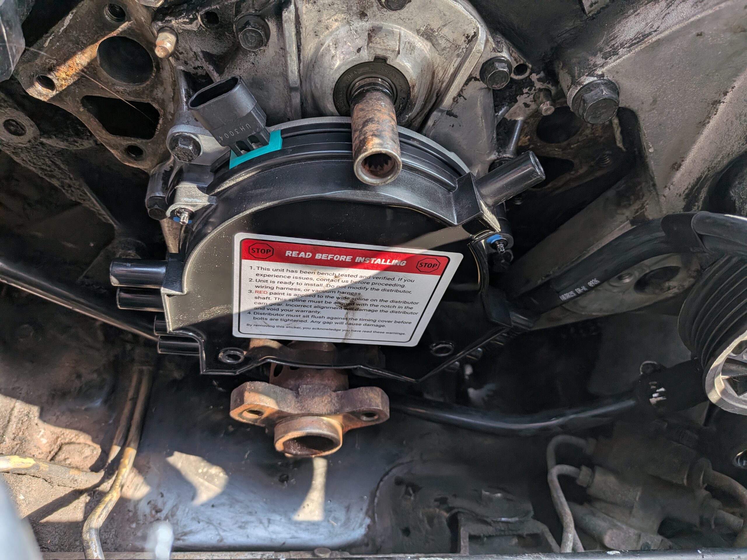
Installing the New Optispark
The Optispark distributor is a precision component, so proper alignment is important.
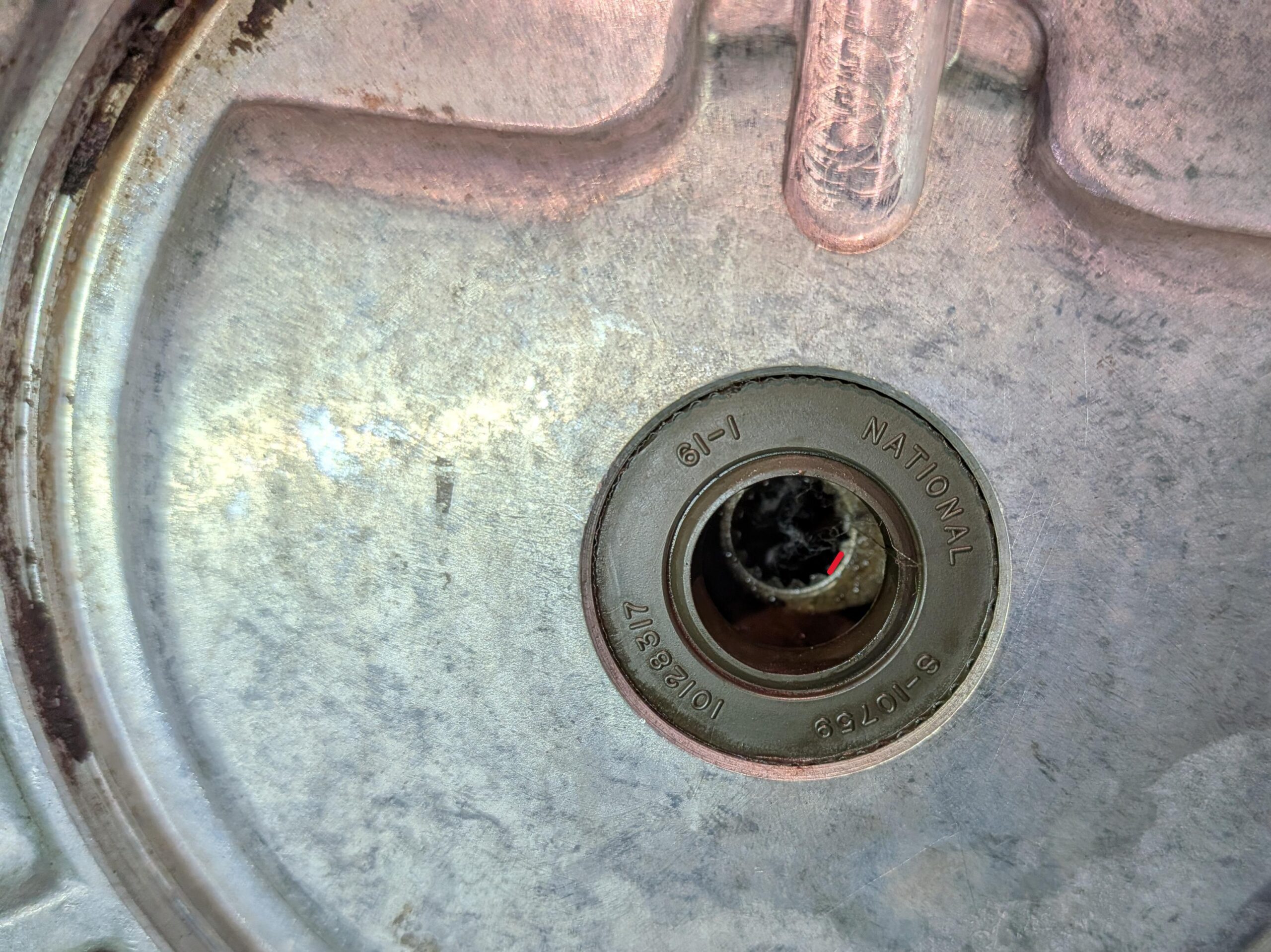
The wide alignment spline on the distributor is marked in red on the Petris Optispark. Rotate the new unit by hand to match the orientation of the distributor that was removed. If you forgot where the spline goes, you can use a phone camera to see inside the timing cover.
When properly aligned, the distributor should slide into place easily. Do not begin tightening the mounting bolts until the distributor sits completely flush against the timing cover. The mounting bolts require only 8 lb-ft of torque.
The Petris Optispark distributor conveniently labels each terminal with its corresponding cylinder number. Take care when installing the spark plug wires, as mixing them up is easy.
Route the passenger-side wires normally. The driver-side wires should be routed along the lower portion of the engine block, away from any pulleys or moving components.
Apply a small amount of dielectric grease to each spark plug boot and ensure every connection is fully seated.
Install the coil wire and route it upward for now—it will later loop over the water pump to reach the ignition coil.
Finally, connect the new four-wire Optispark harness and secure it to the intake.
Reinstalling the Crank Pulley and Belt
Before reinstalling the crank pulley, clean the pulley and crank hub with a scuff pad and apply a thin film of anti-seize. This will make future service easier.
The pulley mounting holes are spaced so it will only install in one orientation.
Install the pulley bolts and tighten them securely, then reinstall the belt tensioner and serpentine belt.
Installing the Water Pump
Install the new water pump the same way the original was removed.
Ensure the gasket surfaces are clean, and use a small amount of RTV sealant to hold the gaskets in place during installation.
You may need to rotate the internal vanes slightly to align the splines with the camshaft drive. When properly aligned, the pump will slide into place with minimal force.
Two alignment dowels on the flange ensure correct positioning.
Install the water pump bolts using liquid thread sealant and torque them to 30 lb-ft.
Final Assembly
Reinstall the thermostat and housing, leaving the bleed screw open for now.
Reconnect the radiator hoses, heater hoses, and all electrical connectors.
Before refilling the cooling system, briefly reconnect the battery and start the engine to confirm everything is operating correctly and there are no unusual noises.
Once everything checks out, refill the cooling system through the surge tank. Continue adding coolant until all the air has bled out of the thermostat housing screw. Monitor the vehicle at idle to make sure there are no coolant leaks from the water pump or any hoses.
Reinstall the intake duct between the air cleaner and throttle body.
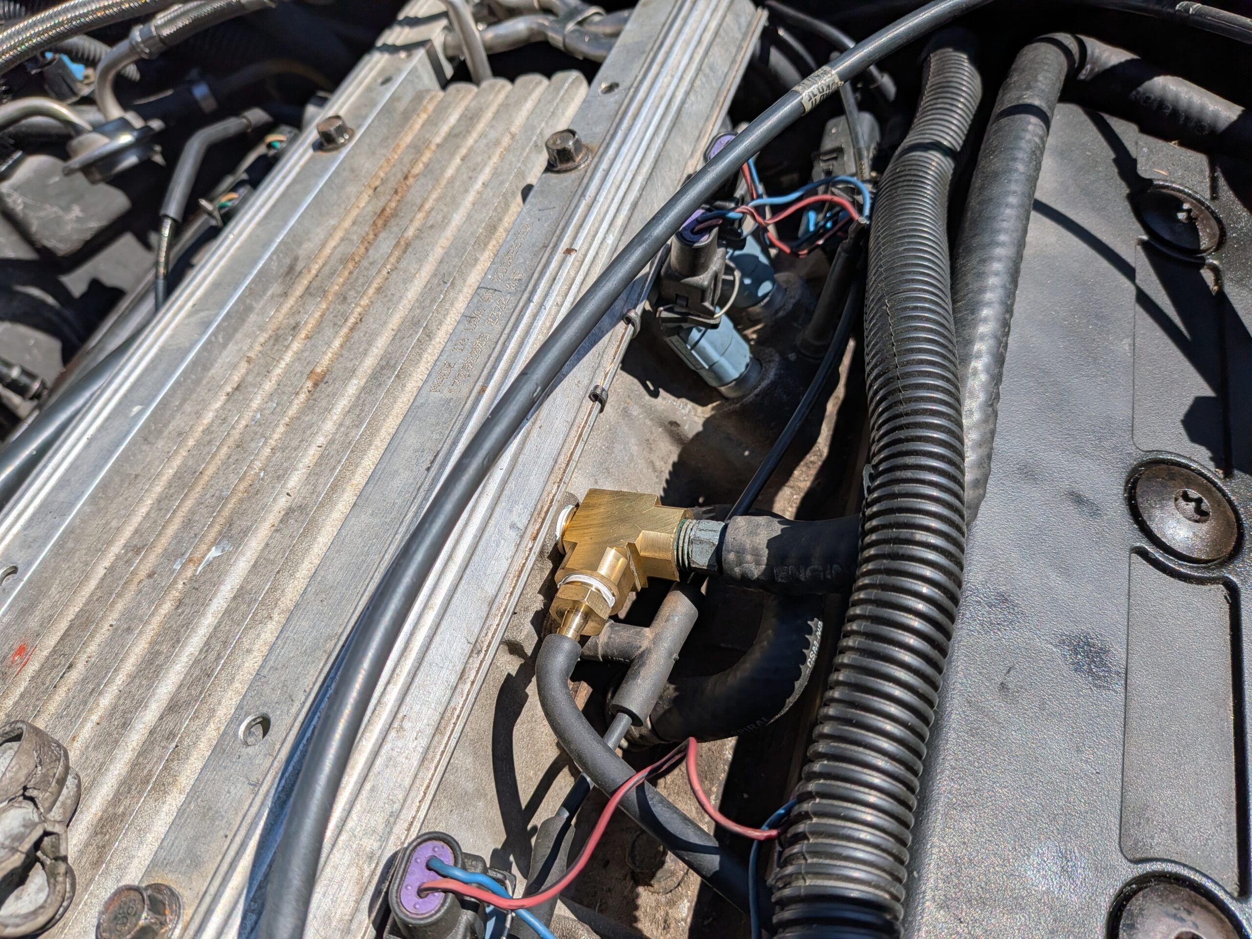
Drill a small 1/8-inch hole in the intake duct to insert the barbed plastic fitting for the smaller Optispark breather hose.
On the driver’s side of the intake, remove the brake booster hose and install the supplied tee fitting. Reconnect the booster hose and attach the larger vent hose.
Back on the Road
With everything reassembled and the cooling system filled, your LT1 Corvette is ready to go.
Replacing the Optispark and water pump at the same time helps eliminate two common failure points and can add years of reliable performance to your Corvette.
Now all that’s left to do is take the car out for a drive and enjoy the results.
8067 Fast Lane | Mechanicsville, VA 23111 | (800) 962-9632
This article is so well written and appreciated. I love that the first step is don’t cheap out and get a good Petris. Buy once cry once.
Great article. easy to follow.
can you please email this to me for future use. I’m all good at this time.