
by Hib Halverson
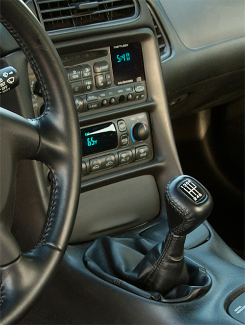
The entertainment system in a C5–let’s just say “radio” from here on–is in the accessory panel at the head of the center console or “center stack” as Corvette engineers call it. Look at the radio’s control panel. Is the faceplate scratched and nicked? Are knobs worn or missing?
Finding a used radio in good condition is nearly impossible. As for a new faceplate, knobs or a complete radio from GM? That might be tough because GM Parts service for many C5 radio pieces has been discontinued.
You can refurbish some of the controls for your C5 Corvette’s radio panel with either replacement of a single knob, a complete knob kit, or a faceplate. Zip Corvette’s reproduction C5 radio parts can return your Corvette’s center stack to factory condition.

This is an example of one of the C5 radio parts Zip has to offer. Below is the full list of parts Zip has available for radio control panel restoration:
- 97-04 Radio Tone / Balance Knob Set
- 97-04 Radio Knob (Small)
- 97-04 Radio Volume Knob
- 97-04 Radio Tune Knob
- 97-04 Radio Trim Plate
- 97-04 Radio Inner Volume Control Knob
- 97-04 Radio Knob Set (Small)
- 97-04 Radio Knob Set (6-piece)
- 97-04 Radio Volume & Tune Knob
Trim Plate and Radio Removal

01: Park the car such that you can open the driver’s door. Disconnect the negative battery cable. Open the console door, remove everything, put it all in a box then store the box in the cargo area or trunk. Next, remove the traction control/ride control panel by pulling up the rear of that panel to release its retainers. Lift it off the Accessory Panel Trim Plate, then turn it over and disconnect the ride/traction control switch harness connector.
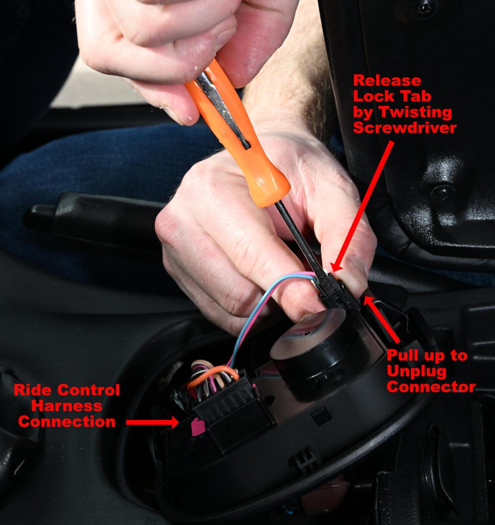
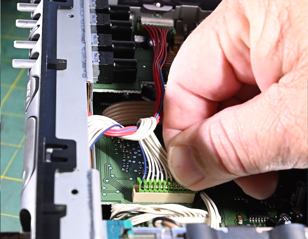
02: The LED Light connecter is difficult to remove. Lay the panel over the space in the Trim Plate with the ride control connection closest to the driver. Use a small screwdriver to release the connector locking tab. While the lock tab is retracted, use your second hand to pull the connector out of the panel. It fits tightly, so grip it firmly. Set the ride and traction control panel aside.

03: Disconnect the wiring to the accessory socket inside the console.

04: There are four 10-mm nuts holding the console, two at the rear and two at the front. The two front nuts are in the space under the ride control panel. Mark the position of the front of the console mounting flange on the rear mounting flange of the Accessory Trim Plate. We used an awl for that, but anything that will make a visible mark on black plastic works. That mark, along with witness marks the washers under front nuts leave on the console’s front mounting flange, will insure that both the Accessory Trim Plate and the Console are returned to the exact positions they were in prior to removal.

05: The two rear nuts are beneath small plastic trim pieces at the rear of the console box. Carefully remove the two trim pieces with a small, flat-blade screwdriver. Then, remove all four nuts holding the console to the torque tube tunnel.
06: Pull the parking brake lever up to gain clearance between it and the Accessory Panel Trim Plate. Pull the console rearward far enough so its front edge clears the rear corners of the Accessory Trim Plate. Typically the console needs to move back about an inch and a half.
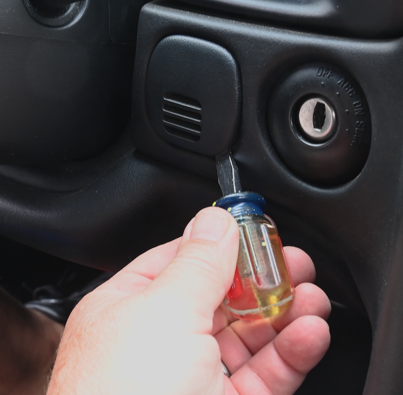
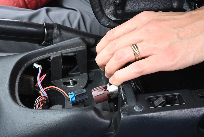
07: Using a short, flat-blade screwdriver, carefully remove the plastic grille to the left of the ignition switch, then remove the 7-mm screw behind it that holds the left end of the Accessory Trim Plate in place on the dashboard.

08: Remove the ashtray. Then, take out two Accessory Trim Plate T5 Torx screws, one next to the accessory socket and another on the ashtray mount.

09: If the car has an automatic trans, select second gear. If the car has a manual trans, shift to fourth. Push the edges of the shift boot retainer inward to free its locking tangs from the Accessory Trim. Lift the boot up, rotate it slightly and tilt it. Leave it in that position.

10: Carefully pull the top of the Accessory Trim Plate rearward to release its upper locking tangs.

11: Then lift the Trim Plate up and over the shift boot.

12: Hold the Trim Plate with one hand. With the other, reach behind the accessory socket and disconnect its wiring harness. Remove the Accessory Trim Plate and set it aside.

13: The radio is retained in the center stack’s aluminum structure by two 7-mm hex screws and a pair of locating pins. Using the 7-mm nut driver, remove those screws. The radio can be a little difficult to remove. It may require gentle prying with two small screw drivers to free it from its locating pins.

14: Pull the radio out of the center stack structure then tip it down. Disconnect the antenna cable. The connection is usually very tight. You may need to pry it loose as shown then pull it the rest of the way by hand. Disconnect the three wiring harnesses.
15: You may find the anti-rattle sponge tape GM sticks on wiring in the center stack and atop the torque tube tunnel has deteriorated. Use a vacuum to remove rotted sponge debris. If you want to replace the sponge tape, it is available from a variety of Internet vendors. A problem can be its availability in only large quantities when you only need a couple of feet of tape.
16: Put the radio on your workbench. To prevent damage, rest it on a towel or a sheet of bubble wrap
Radio Faceplate and Knobs Replacement
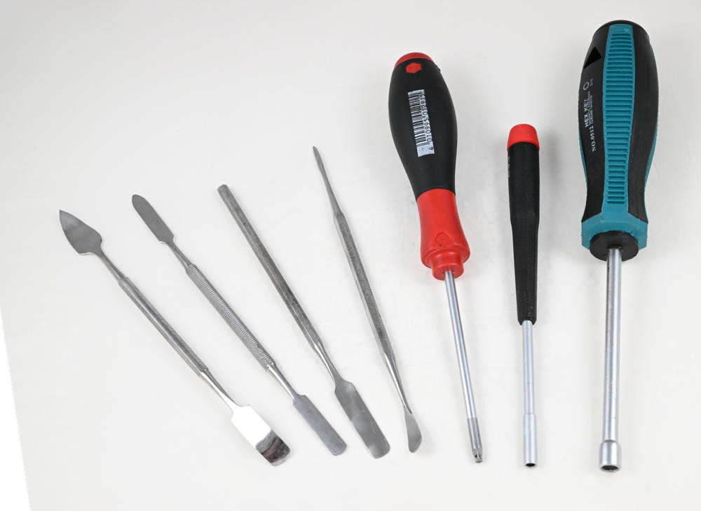
17: The next steps require partial disassembly of the radio. The task requires tools not common to most Corvette DIY toolboxes. You need ⅛-in and 3/16-in nut drivers plus a T5 Torx driver. You also need some tweezers and a set of small spatulas typically used for arts-and-crafts, electronics service and jewelry making. Vendors that sell tools for electronic service work are good sources for those tools.

18: Pull the volume, tuning, balance, fade, and tone knobs off their shafts.

19: The faceplate is held by eight plastic locking tabs. Use a small screwdriver to lift each tab up just enough to release it. First, do the lock tabs that hold each top corner of the faceplate. We unlocked the first corner, then placed a flat washer–any shimming device will work–between the face plate and the radio frame to prevent the tabs from relocking. Once the first washer was in place, we released the other two corner locks and put a second washer in place.

20: With washers holding the four tabs unlocked, turn the radio upside down and, using the 3/16 nut driver and the T5, remove the three screws holding the bottom plate.

21: Remove the bottom plate.

22: Unplug the two wiring harnesses that lead inside the radio. The plugs might be tight, but they are very small, so be careful about applying force to disconnect them.

23: Unlock the remaining tabs holding the bottom of the faceplate to the radio. Then, while carefully feeding the wiring through the passage in the front of the radio, remove the faceplate assembly.

24: Using a 7/16-in., quarter-inch-drive deep socket, remove the lock nut on the volume control shaft.

25: Place the faceplate face down on a soft surface and, using the ⅛-inch nut driver, remove the seven hex screws holding the PC board to the faceplate, then separate the two and set the PC board aside.

26: Take a picture or draw a diagram of the radio faceplate so you know the position of the buttons when you transfer them to the new faceplate.

27: Separate the faceplate from its PC board and set the board aside.

28: Turn the faceplate over, then orient it with the top pointing away from you. Inside the faceplate is a white plastic piece that retains the radio buttons. It is held in place with locking tabs. Release the right-side lock tab with your thumb.

29: Lift the right end of the button retainer and pull it to the right to release the other lock tab. Set the button retainer aside.

30: On the lower left part of the faceplate, above the wells for the balance and tone controls, is a clear plastic insert that is part of radio lighting. Remove it and set it aside.

31: In the same area, below the display lens location, is a small square of transparent blue plastic and a sponge rubber pad. Use one of your spatula tools to remove both.

32: Remove three buttons below the sponge pads. The “HR” and “MN” buttons are tiny. Tweezers make getting them out easier.

33: On top of the rest of the buttons is a sheet of transparent blue plastic and a layer of sponge rubber located by two vertical posts. Most spatula kits include a tool that is a sort of “pry bar.’ You may need that to lift the sponge rubber off those posts.

34: Remove the rest of the buttons. Again, a pair of tweezers is your friend.

35: On the upper right part of the interior of the face plate is a second clear plastic insert that is also part of the radio lighting. It’s retained by several locking tabs. This insert is difficult to remove. We used the “pry bar” to lift the upper end of it, then carefully rotate it out of the locking tabs.

36: Lift the top of the metal plate that locates the volume shaft with your “pry bar” then lift it out with your fingers.

37: Remove the new 97-04 Radio Trim Plate from the Zip Corvette packaging.

38: Place the new faceplate face down, top pointing away from you. Then install the volume control locking plate.

39: Reinstall the right-side lighting insert. Like the removal, this step can be tricky.

40: Install the buttons. Refer to your image or diagram of the button locations if necessary.

41: Add the sponge rubber sections over the buttons followed by the two sections of transparent blue plastic. You may need your “pry bar” to push the two onto the locating posts.

42: Set the lighting insert in place above the wells for the balance and tone controls.

43: Push the white plastic button retaining plate back into its locks.

44: The blue plastic part, the purpose of which we can’t identify, is installed with its “feet” pointing down into locating slots on the button retainer.

45: Lay the PC board, bulbs pointing down, onto the faceplate.

46: Reinstall the seven hex screws with the ⅛-in nut driver.

47: Replace the volume control shaft lock nut using the 7/16-in. quarter-drive deep socket, then push the faceplate back onto the front of the radio. Make sure all the tabs are locked.

48: Feed the faceplate wiring harnesses through the opening in the front of the radio chassis.

49: Push and lock the faceplate onto the radio chassis.
50: Plug the faceplate wiring harnesses back into their sockets inside the radio chassis.

51: Replace the radio bottom plate.

52: Turn the radio right side up and install the fade, balance, bass and treble knobs (97-04 Small Radio Knob Set) followed by the inner and outer volume knobs and the tuning knob (97-04 Radio Inner Volume Control Knob, 97-04 Radio Volume Knob, 97-04 Radio Tune Knob or 97-04 6-Piece Radio Knob Set). Peel off the protective film on the display lens.

53: Restored radio ready for installation.
Reinstallation of Radio Control Panel and Accessory Panel Trim

54: Reconnect the radio antenna. Make sure the antenna plug is pushed all the way into the socket on the back of the radio.

55: Reconnect the three wiring harnesses. On the back of the radio is a plastic locating pin which goes into a socket in the center stack structure behind the radio. When pushing the radio into the mount, it’s possible to have the harness wrap over the pin and get stuck between the back of the radio and the structure. You may need to reach behind the radio with your fingers and hold the wires away from the pin while carefully pushing the radio with your other hand.

56: Then, get your hand out of the way and push the radio until the holes in the radio’s two mounting brackets line up with the locating pins in the center stack structure.

57: Reinstall the radio’s two 7-mm hex head screws.

58: If your C5’s Accessory Panel Trim Plate is damaged or worn, Zip Corvette sells a reproduction 97-04 Center Dash Console Assembly. It comes with a new ashtray door and cup holder insert. The part is black with the correct grain. For interior colors other than black, it must be painted to match using paint intended for automotive interior plastics.

59: To install the Accessory Trim Panel, confirm that the center console has been moved back far enough. The shift boot needs to be rotated and tilted, then lower the Accessory Trim over the shift boot and onto the torque tube tunnel.

60: Reconnect the accessory socket’s wiring harness by snapping it into place.

61: Push the panel’s two upper mounting tabs into their slots above the radio.

62: Push the Accessory Trim Plate back into place, then pull the Console forward, back into position, such that the front of it overlaps the rear of the Accessory Panel Trim Plate.

63: Reinstall the two T5 Torx screws into the holes in the ashtray cavity.

64: Reinstall the 7-mm hex screw into the well next to the ignition switch and replace the grille.

65: Adjust the Accessory Panel Trim and the Console position to the marks you made previously. Reinstall the four 10-mm hex nuts that secure the center console and put the plastic trim covers back in place over the rear two nuts.

66: Slide the shift boot down, align it with its mounting, then push down on the edges to lock it in place.

67: Retrieve the ride control switch panel. Reconnect its wiring harnesses and reconnect the glove box light harness.

68: Push the ride control panel back into place. Replace items removed from the center console compartment. Reconnect the negative battery cable.

69: Start the engine and take the car for a road test to verify that the radio is working correctly.
1997-2004 Corvette Radio Control Panel Refurbishment
Source: Zip Corvette Parts
8067 Fast Lane | Mechanicsville, VA 23111 | (800) 962-9632
Corvette Parts List Related to Article:
- 97-04 Radio Tone / Balance Knob Set
- 97-04 Radio Knob (Small)
- 97-04 Radio Volume Knob
- 97-04 Radio Tune Knob
- 97-04 Radio Trim Plate
- 97-04 Radio Inner Volume Control Knob
- 97-04 Radio Knob Set (Small)
- 97-04 Radio Knob Set (6-piece)
- 97-04 Radio Volume & Tune Knob
- 97-04 Center Dash Console Assembly
- Shop/Service Manuals